3.Tighten lock knob. Make sure blade guide blocks (C, Figure 30) are still flat to the blade. If adjustment is necessary, loosen lock knob (A, Figure 30) and rotate assembly until guide blocks are flat to blade.
4.If movement of the blade guide assembly seems “stiff” when being raised or lowered, it can be adjusted to slide more easily. This is controlled by an internal spring and ball which provide varying degrees of resistance against the guide post. Use the set screw (D, Figure 30) to adjust the tension of this spring. To adjust tension on the spring, loosen knob (A, Figure 30), use a hex wrench to tighten or loosen set screw (D, Figure 30) until desired tension is reached, then
Adjusting Blade Guide and Blade
Support Bearing
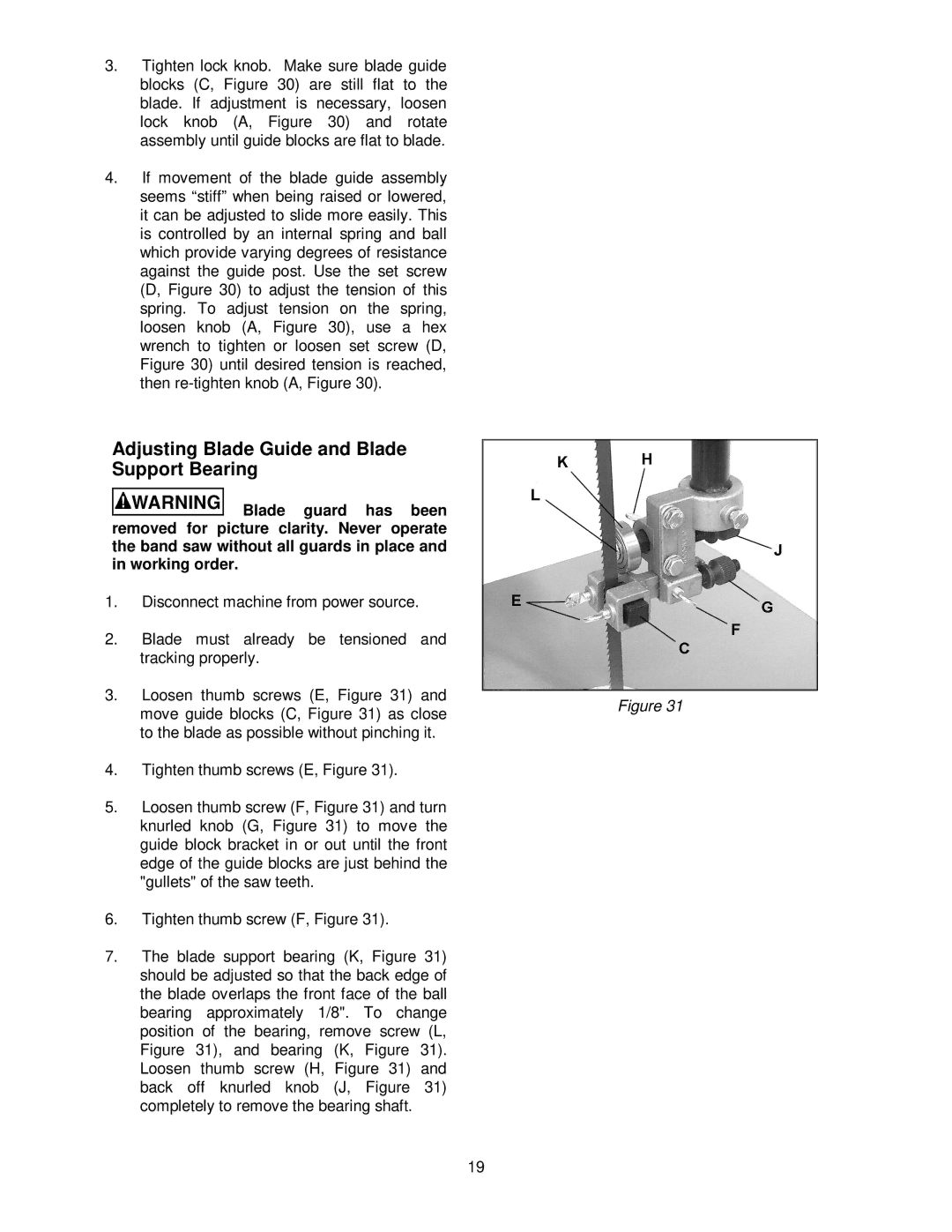
![]() Blade guard has been removed for picture clarity. Never operate the band saw without all guards in place and in working order.
Blade guard has been removed for picture clarity. Never operate the band saw without all guards in place and in working order.
1. | Disconnect machine from power source. |
|
2. | Blade must already be tensioned and |
|
| tracking properly. |
|
3. | Loosen thumb screws (E, Figure 31) and | Figure 31 |
| move guide blocks (C, Figure 31) as close | |
|
|
to the blade as possible without pinching it.
4.Tighten thumb screws (E, Figure 31).
5.Loosen thumb screw (F, Figure 31) and turn knurled knob (G, Figure 31) to move the guide block bracket in or out until the front edge of the guide blocks are just behind the "gullets" of the saw teeth.
6.Tighten thumb screw (F, Figure 31).
7.The blade support bearing (K, Figure 31) should be adjusted so that the back edge of the blade overlaps the front face of the ball bearing approximately 1/8". To change position of the bearing, remove screw (L, Figure 31), and bearing (K, Figure 31). Loosen thumb screw (H, Figure 31) and back off knurled knob (J, Figure 31) completely to remove the bearing shaft.
19