IMPORTANT: When moving the pulleys, do not position them beyond the end of the shaft. Both pulleys must fully engage the shaft and the key.
7.Open the lower door, and place the
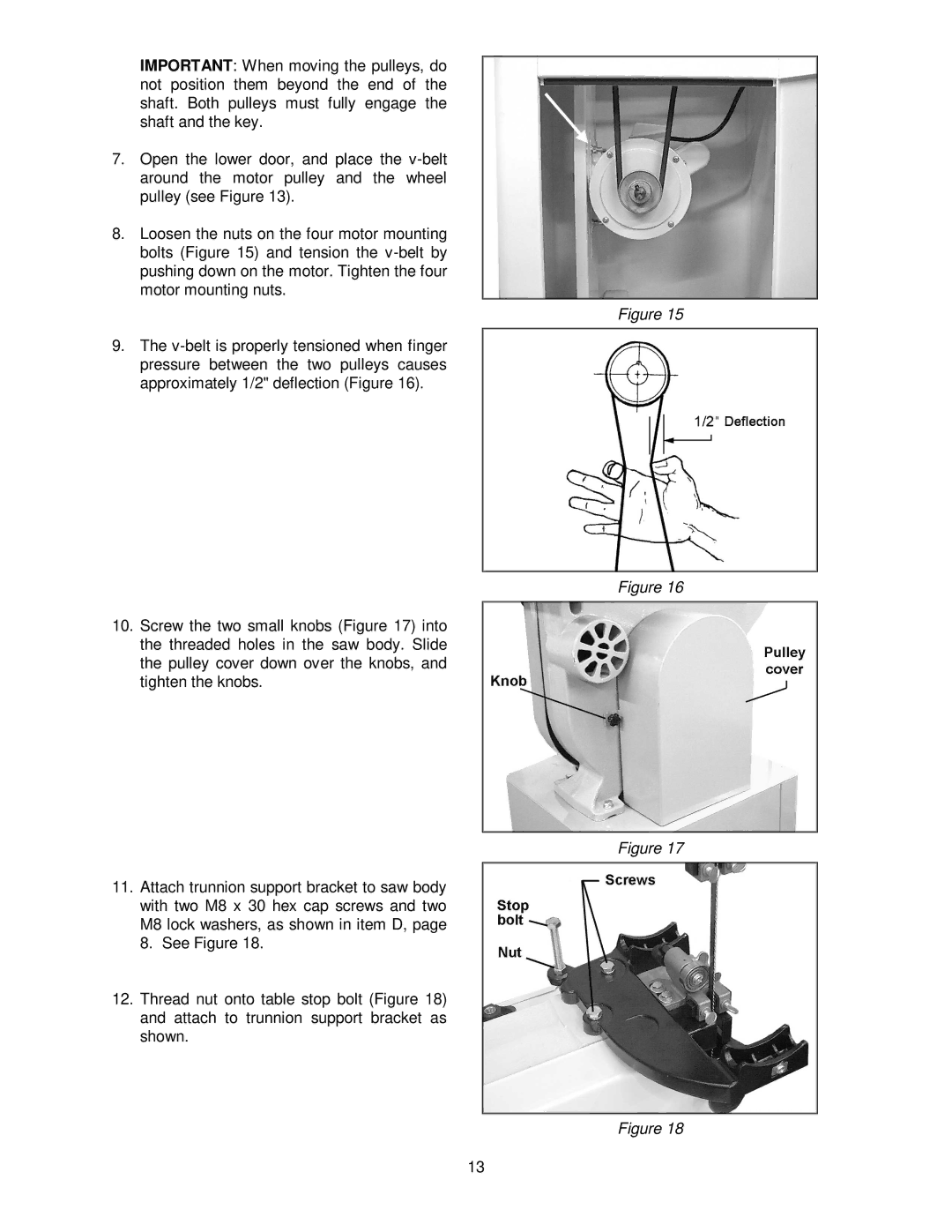
8.Loosen the nuts on the four motor mounting bolts (Figure 15) and tension the
Figure 15
9.The
Figure 16
10.Screw the two small knobs (Figure 17) into the threaded holes in the saw body. Slide the pulley cover down over the knobs, and tighten the knobs.
Figure 17
11.Attach trunnion support bracket to saw body with two M8 x 30 hex cap screws and two M8 lock washers, as shown in item D, page 8. See Figure 18.
12.Thread nut onto table stop bolt (Figure 18) and attach to trunnion support bracket as shown.
Figure 18
13
