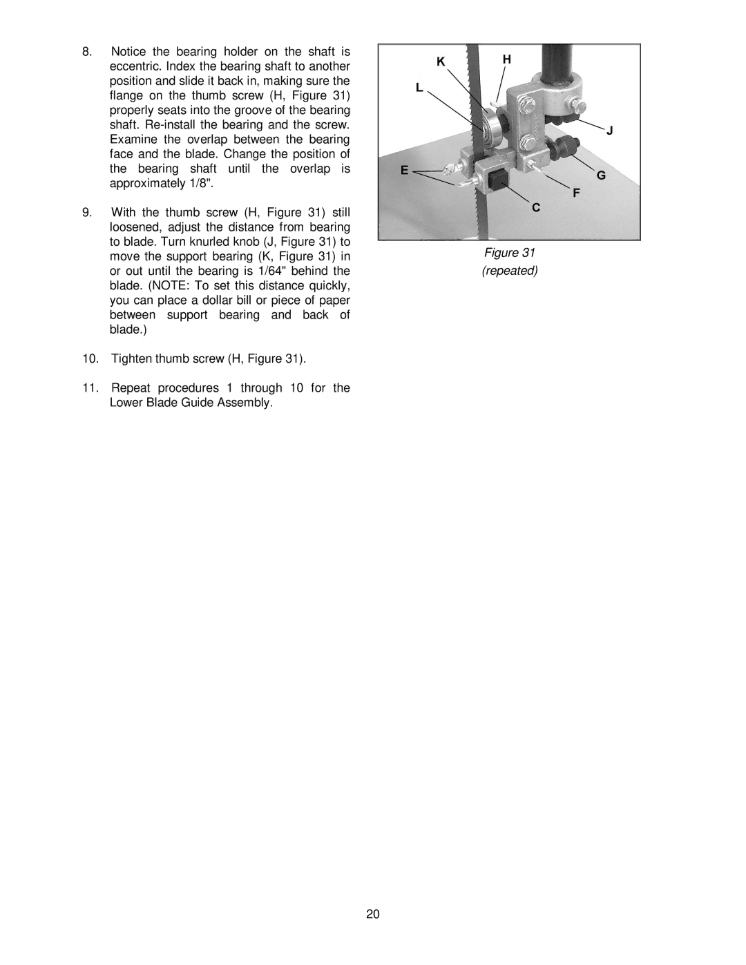
8.Notice the bearing holder on the shaft is eccentric. Index the bearing shaft to another position and slide it back in, making sure the flange on the thumb screw (H, Figure 31) properly seats into the groove of the bearing shaft.
9.With the thumb screw (H, Figure 31) still loosened, adjust the distance from bearing to blade. Turn knurled knob (J, Figure 31) to move the support bearing (K, Figure 31) in or out until the bearing is 1/64" behind the blade. (NOTE: To set this distance quickly, you can place a dollar bill or piece of paper between support bearing and back of blade.)
10.Tighten thumb screw (H, Figure 31).
11.Repeat procedures 1 through 10 for the Lower Blade Guide Assembly.
Figure 31
(repeated)
20
