J2500.1 specifications
The JL Audio J2500.1 is a powerful monoblock amplifier primarily designed for serious music enthusiasts and audiophiles who demand high-quality sound reproduction in their car audio systems. With a robust output of 2500 watts RMS at 1 ohm, this amplifier is engineered to deliver deep, thunderous bass without sacrificing clarity or detail.One of the standout features of the J2500.1 is its patented NexD technology, which allows for efficient and precise power delivery. This technology optimizes the amplifier's performance, minimizing distortion and maximizing sound fidelity. The amp's efficient Class D design not only contributes to lower power consumption but also helps in keeping the unit relatively cool during prolonged use, avoiding overheating issues that can plague less efficient amplifiers.
The amplifier is equipped with advanced thermal management features, including internal temperature sensing and a built-in fan for additional cooling when required. This ensures that the J2500.1 can perform optimally, even under the most demanding conditions.
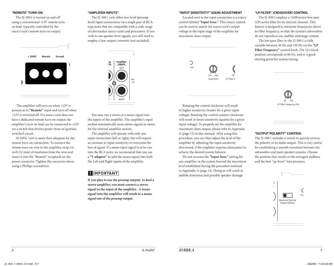
Another significant characteristic of the JL Audio J2500.1 is its adjustable low-pass filter, which allows users to tailor the frequency response to suit their specific audio needs. The filter can be set between 30 Hz and 200 Hz, enabling seamless integration with subwoofers and other components in a car audio setup. Additionally, it features both a variable bass boost and a subsonic filter, offering further control over the audio output to enhance the listening experience.
The amplifier's construction boasts durability and sophistication, featuring a rigid chassis and high-quality components designed to withstand vibration and harsh automotive environments. Its sleek aesthetic, combined with practical terminal placement, makes installation straightforward, catering to both professional installers and passionate DIY enthusiasts.
In essence, the JL Audio J2500.1 is engineered for those seeking uncompromising performance and scalability in their sound systems. With its powerful output, advanced technologies, and user-friendly features, it stands out as a premier choice for delivering exceptional audio quality, especially for bass enthusiasts looking to elevate their in-car music experience. Whether used in a dedicated subwoofer setup or as a part of a more complex audio system, the J2500.1 will undoubtedly impress even the most discerning listeners.

