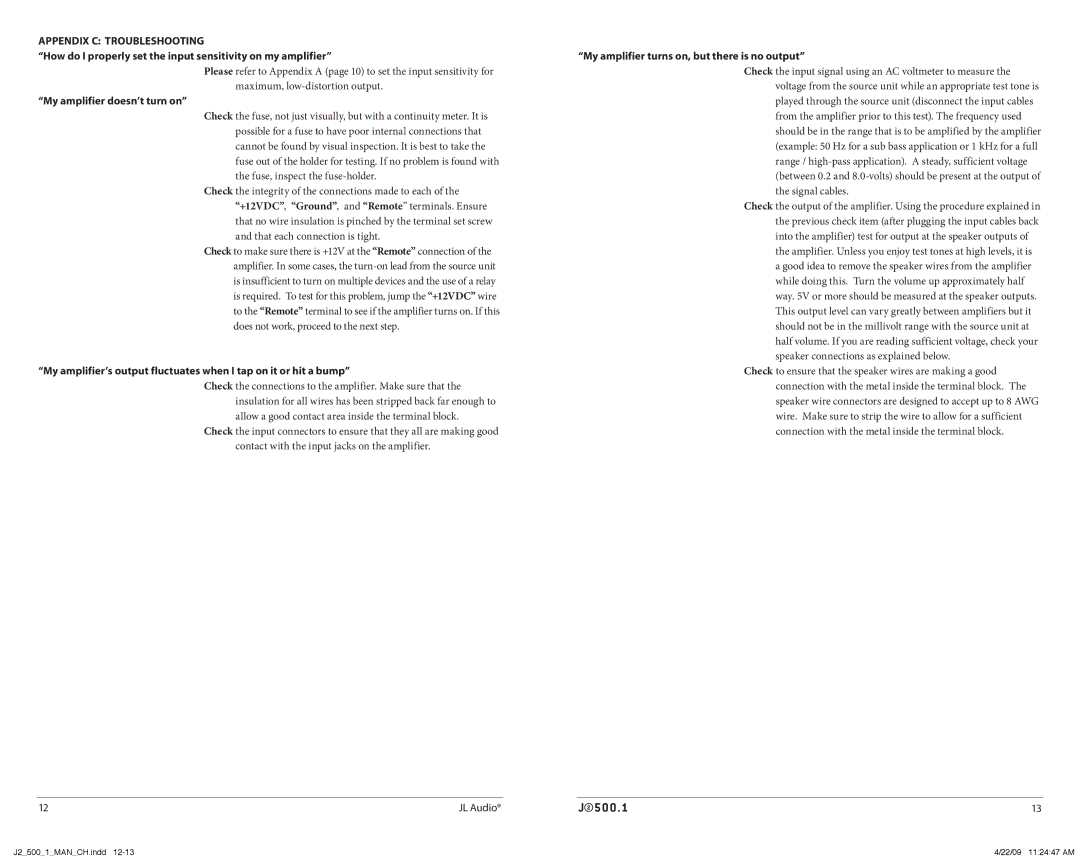
Appendix c: TROUBLESHOOTING

“How do I properly set the input sensitivity on my amplifier”

Please refer to Appendix A (page 10) to set the input sensitivity for maximum, low-distortion output.

“My amplifier doesn’t turn on”

Check the fuse, not just visually, but with a continuity meter. It is possible for a fuse to have poor internal connections that cannot be found by visual inspection. It is best to take the fuse out of the holder for testing. If no problem is found with the fuse, inspect the fuse-holder.

Check the integrity of the connections made to each of the “+12VDC”, “Ground”, and “Remote” terminals. Ensure that no wire insulation is pinched by the terminal set screw and that each connection is tight.

Check to make sure there is +12V at the “Remote” connection of the amplifier. In some cases, the turn-on lead from the source unit is insufficient to turn on multiple devices and the use of a relay is required. To test for this problem, jump the “+12VDC” wire to the “Remote” terminal to see if the amplifier turns on. If this does not work, proceed to the next step.

“My amplifier’s output fluctuates when I tap on it or hit a bump”

Check the connections to the amplifier. Make sure that the insulation for all wires has been stripped back far enough to allow a good contact area inside the terminal block.

Check the input connectors to ensure that they all are making good contact with the input jacks on the amplifier.

“My amplifier turns on, but there is no output”

Check the input signal using an AC voltmeter to measure the voltage from the source unit while an appropriate test tone is played through the source unit (disconnect the input cables from the amplifier prior to this test). The frequency used should be in the range that is to be amplified by the amplifier (example: 50 Hz for a sub bass application or 1 kHz for a full range / high-pass application). A steady, sufficient voltage (between 0.2 and 8.0-volts) should be present at the output of the signal cables.

Check the output of the amplifier. Using the procedure explained in the previous check item (after plugging the input cables back into the amplifier) test for output at the speaker outputs of the amplifier. Unless you enjoy test tones at high levels, it is a good idea to remove the speaker wires from the amplifier while doing this. Turn the volume up approximately half way. 5V or more should be measured at the speaker outputs. This output level can vary greatly between amplifiers but it should not be in the millivolt range with the source unit at half volume. If you are reading sufficient voltage, check your speaker connections as explained below.

Check to ensure that the speaker wires are making a good connection with the metal inside the terminal block. The speaker wire connectors are designed to accept up to 8 AWG wire. Make sure to strip the wire to allow for a sufficient connection with the metal inside the terminal block.

12

JL Audio®

13

J2_500_1_MAN_CH.indd 12-13

4/22/09 11:24:47 AM

Page 7
Image 7
JL Audio J2500.1 owner manual My amplifier doesn’t turn on, My amplifier turns on, but there is no output

J2500.1 specifications

The JL Audio J2500.1 is a powerful monoblock amplifier primarily designed for serious music enthusiasts and audiophiles who demand high-quality sound reproduction in their car audio systems. With a robust output of 2500 watts RMS at 1 ohm, this amplifier is engineered to deliver deep, thunderous bass without sacrificing clarity or detail.

One of the standout features of the J2500.1 is its patented NexD technology, which allows for efficient and precise power delivery. This technology optimizes the amplifier's performance, minimizing distortion and maximizing sound fidelity. The amp's efficient Class D design not only contributes to lower power consumption but also helps in keeping the unit relatively cool during prolonged use, avoiding overheating issues that can plague less efficient amplifiers.

The amplifier is equipped with advanced thermal management features, including internal temperature sensing and a built-in fan for additional cooling when required. This ensures that the J2500.1 can perform optimally, even under the most demanding conditions.

Another significant characteristic of the JL Audio J2500.1 is its adjustable low-pass filter, which allows users to tailor the frequency response to suit their specific audio needs. The filter can be set between 30 Hz and 200 Hz, enabling seamless integration with subwoofers and other components in a car audio setup. Additionally, it features both a variable bass boost and a subsonic filter, offering further control over the audio output to enhance the listening experience.

The amplifier's construction boasts durability and sophistication, featuring a rigid chassis and high-quality components designed to withstand vibration and harsh automotive environments. Its sleek aesthetic, combined with practical terminal placement, makes installation straightforward, catering to both professional installers and passionate DIY enthusiasts.

In essence, the JL Audio J2500.1 is engineered for those seeking uncompromising performance and scalability in their sound systems. With its powerful output, advanced technologies, and user-friendly features, it stands out as a premier choice for delivering exceptional audio quality, especially for bass enthusiasts looking to elevate their in-car music experience. Whether used in a dedicated subwoofer setup or as a part of a more complex audio system, the J2500.1 will undoubtedly impress even the most discerning listeners.