S T E P 2 0
alignment of the front of each pod, once both front and rear alignment is achieved, use a marker to make marks on the masking tape shown in STEP 17 through the holes in the pods identified in STEP 18.
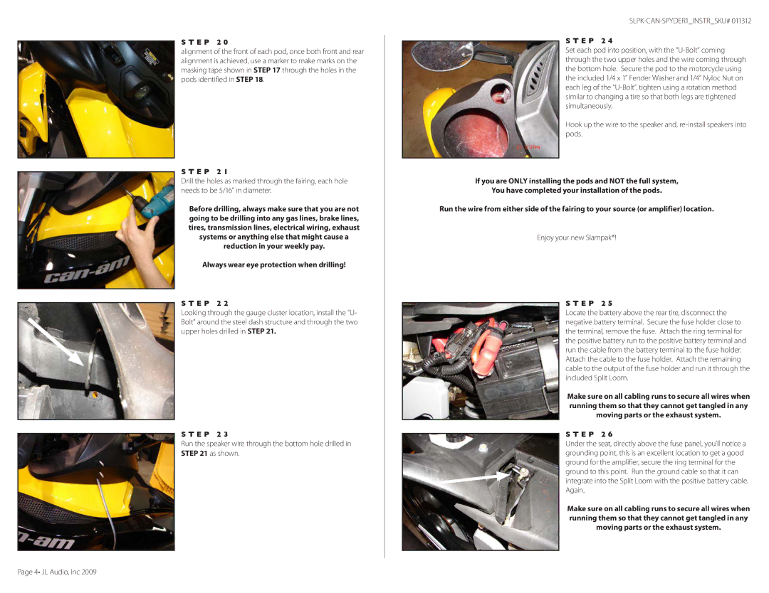
S T E P 2 1
Drill the holes as marked through the fairing, each hole needs to be 5/16” in diameter.
Before drilling, always make sure that you are not going to be drilling into any gas lines, brake lines, tires, transmission lines, electrical wiring, exhaust systems or anything else that might cause a reduction in your weekly pay.
Always wear eye protection when drilling!
S T E P 2 2
Looking through the gauge cluster location, install the “U- Bolt” around the steel dash structure and through the two upper holes drilled in STEP 21.
S T E P 2 3
Run the speaker wire through the bottom hole drilled in STEP 21 as shown.
S T E P 2 4
Set each pod into position, with the
Hook up the wire to the speaker and,
If you are ONLY installing the pods and NOT the full system,
You have completed your installation of the pods.
Run the wire from either side of the fairing to your source (or amplifier) location.
Enjoy your new Slampak®!
S T E P 2 5
Locate the battery above the rear tire, disconnect the negative battery terminal. Secure the fuse holder close to the terminal, remove the fuse. Attach the ring terminal for the positive battery run to the positive battery terminal and run the cable from the battery terminal to the fuse holder. Attach the cable to the fuse holder. Attach the remaining cable to the output of the fuse holder and run it through the included Split Loom.
Make sure on all cabling runs to secure all wires when running them so that they cannot get tangled in any moving parts or the exhaust system.
S T E P 2 6
Under the seat, directly above the fuse panel, you’ll notice a grounding point, this is an excellent location to get a good ground for the amplifier, secure the ring terminal for the ground to this point. Run the ground cable so that it can integrate into the Split Loom with the positive battery cable. Again,
Make sure on all cabling runs to secure all wires when running them so that they cannot get tangled in any moving parts or the exhaust system.
Page 4• JL Audio, Inc 2009