CONNECTION TO CYLINDER & WATER HEATERS CONTINUED
Unvented pressurised cylinders can be installed using Speedfit Pipe and Fittings. However, insertion depths on compression joints that form part of the cylinder must be checked prior to installation and the use of standard pipe inserts (Prefix TSM) is recommended.
In accordance with current U.K. Building Regulations (Part G), discharge pipes from temperature and/or pressure relief valves must be run in metal pipework.
Speedfit connections to combined Cylinder/Boiler units and Thermal Storage Units must be made outside the casing unless otherwise stated in manufacturers installation literature.
CONNECTION TO PUMPS AND VALVES
Speedfit pipe should be connected to circulating pumps, motorised valves in accordance with the section in this book headed, “Connecting Plastic Pipe To Compression Fittings”. If Speedfit pipe is not mounted on a supporting structure, the pipe must be clipped close to the components’ connections to ensure adequate support and to assist in the reduction of vibration.
For heavier equipment, ensure that appropriate metal brackets provide full and independent support of the components and that it does not rely solely on the pipework for support.
WATER HEATERS
Speedfit recommend that mains supply pipework to unvented water heaters (up to 15ltr capacity), be run in metal pipes.
UNVENTED PRESSURISED CYLINDERS
Unvented Pressurised Cylinders can be installed using Speedfit pipe and fittings. However if the safety
ELECTRICAL CONTINUITY CONT’D
IEE Guidance Note 7 provides useful guidance on the design of electrical installations where there is increased risk of electric shock. It recognises that the requirement for supplementry bonding may be relaxed where metal taps and plastic pipes supply other bathroom fittings.
Similarly a metal bath or radiator not connected to an extraneous-conductive-part is not required to be connected to the local supplementry conductors.
| Clip | Earth Lead | Clip |
Metal | |
| | Metal |
Pipe | | Speedfit Pipe and Fitting | Pipe |
| | |
SUPPLEMENTRY BONDING TO BATHROOMS
INSTALLING PIPEWORK
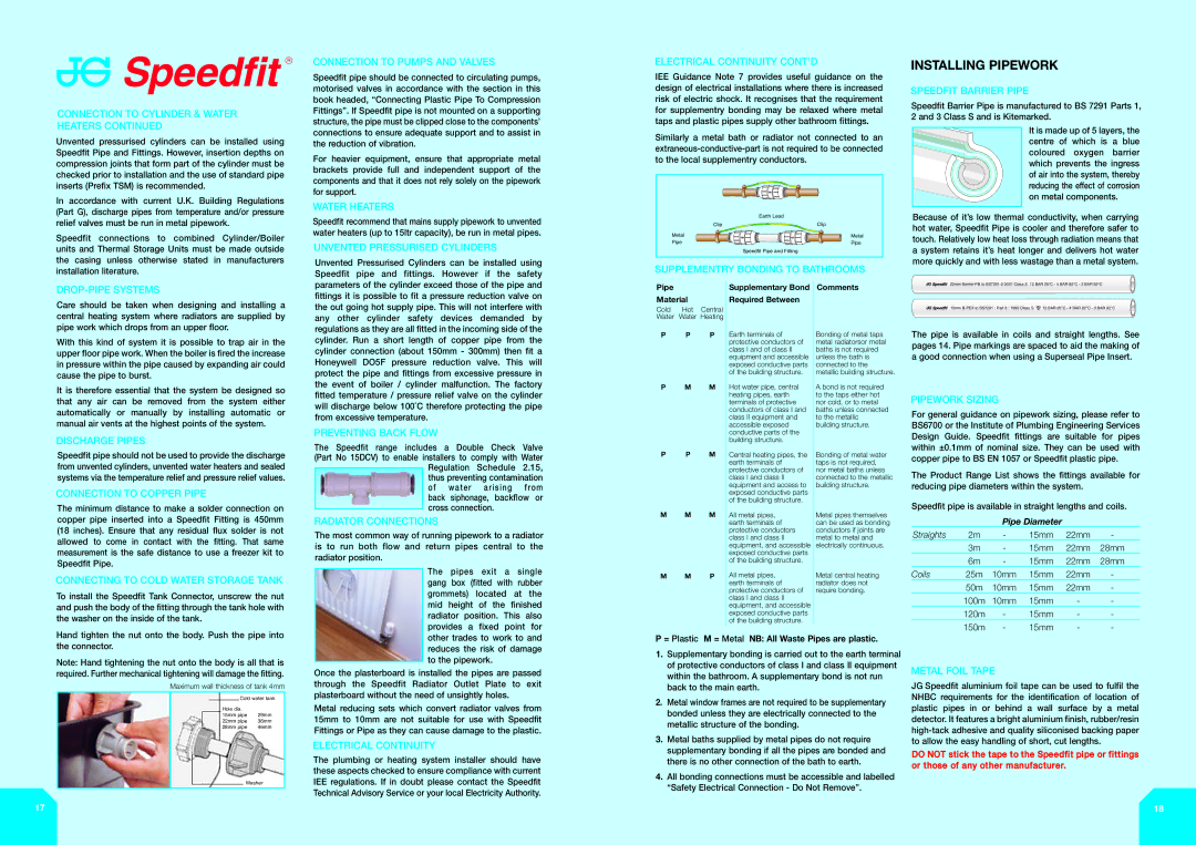
SPEEDFIT BARRIER PIPE
Speedfit Barrier Pipe is manufactured to BS 7291 Parts 1, 2 and 3 Class S and is Kitemarked.
It is made up of 5 layers, the centre of which is a blue coloured oxygen barrier which prevents the ingress of air into the system, thereby reducing the effect of corrosion on metal components.
Because of it’s low thermal conductivity, when carrying hot water, Speedfit Pipe is cooler and therefore safer to touch. Relatively low heat loss through radiation means that a system retains it’s heat longer and delivers hot water more quickly and with less wastage than a metal system.
DROP-PIPE SYSTEMS
Care should be taken when designing and installing a central heating system where radiators are supplied by pipe work which drops from an upper floor.
With this kind of system it is possible to trap air in the upper floor pipe work. When the boiler is fired the increase in pressure within the pipe caused by expanding air could cause the pipe to burst.
It is therefore essential that the system be designed so that any air can be removed from the system either automatically or manually by installing automatic or manual air vents at the highest points of the system.
DISCHARGE PIPES
Speedfit pipe should not be used to provide the discharge from unvented cylinders, unvented water heaters and sealed systems via the temperature relief and pressure relief values.
CONNECTION TO COPPER PIPE
The minimum distance to make a solder connection on copper pipe inserted into a Speedfit Fitting is 450mm (18 inches). Ensure that any residual flux solder is not allowed to come in contact with the fitting. That same measurement is the safe distance to use a freezer kit to Speedfit Pipe.
CONNECTING TO COLD WATER STORAGE TANK
To install the Speedfit Tank Connector, unscrew the nut and push the body of the fitting through the tank hole with the washer on the inside of the tank.
parameters of the cylinder exceed those of the pipe and fittings it is possible to fit a pressure reduction valve on the out going hot supply pipe. This will not interfere with any other cylinder safety devices demanded by regulations as they are all fitted in the incoming side of the cylinder. Run a short length of copper pipe from the cylinder connection (about 150mm - 300mm) then fit a Honeywell DO5F pressure reduction valve. This will protect the pipe and fittings from excessive pressure in the event of boiler / cylinder malfunction. The factory fitted temperature / pressure relief valve on the cylinder will discharge below 100˚C therefore protecting the pipe from excessive temperature.
PREVENTING BACK FLOW
The Speedfit range includes a Double Check Valve (Part No 15DCV) to enable installers to comply with Water Regulation Schedule 2.15, thus preventing contamination of water arising from back siphonage, backflow or
cross connection.
RADIATOR CONNECTIONS
The most common way of running pipework to a radiator is to run both flow and return pipes central to the radiator position.
The pipes exit a single gang box (fitted with rubber grommets) located at the mid height of the finished radiator position. This also provides a fixed point for
Pipe
Material
Cold Hot Central Water Water Heating
P P P
P M M
P P M
M M M
M M P
Supplementary Bond Required Between
Earth terminals of protective conductors of class I and of class II equipment and accessible exposed conductive parts of the building structure.
Hot water pipe, central heating pipes, earth terminals of protective conductors of class I and class II equipment and accessible exposed conductive parts of the building structure.
Central heating pipes, the earth terminals of protective conductors of class I and class II equipment and access to exposed conductive parts of the building structure.
All metal pipes, earth terminals of protective conductors class I and class II equipment, and accessible exposed conductive parts of the building structure.
All metal pipes, earth terminals of protective conductors of class I and class II equipment, and accessible exposed conductive parts of the building structure.
Comments
Bonding of metal taps metal radiatorsor metal baths is not required unless the bath is connected to the metallic building structure.
A bond is not required to the taps either hot nor cold, or to metal baths unless connected to the metallic building structure.
Bonding of metal water taps is not required, nor metal baths unless connected to the metallic building structure.
Metal pipes themselves can be used as bonding conductors if joints are metal to metal and electrically continuous.
Metal central heating radiator does not require bonding.
22mm Barrier-PB to BS7291-2 2001 Class S 12 BAR 20°C - 4 BAR 82°C - 3 BAR 92°C


 15mm B-PEX to BS7291 : Part 3 : 1990 Class S
  12 BAR 20°C - 4 BAR 82°C - 3 BAR 92°C
The pipe is available in coils and straight lengths. See pages 14. Pipe markings are spaced to aid the making of a good connection when using a Superseal Pipe Insert.
PIPEWORK SIZING
For general guidance on pipework sizing, please refer to BS6700 or the Institute of Plumbing Engineering Services Design Guide. Speedfit fittings are suitable for pipes within ±0.1mm of nominal size. They can be used with copper pipe to BS EN 1057 or Speedfit plastic pipe.
The Product Range List shows the fittings available for reducing pipe diameters within the system.
Speedfit pipe is available in straight lengths and coils.
Pipe Diameter
Straights | 2m | - | 15mm | 22mm | - |
| 3m | - | 15mm | 22mm | 28mm |
| 6m | - | 15mm | 22mm | 28mm |
Coils | 25m | 10mm | 15mm | 22mm | - |
| 50m | 10mm | 15mm | 22mm | - |
| 100m | 10mm | 15mm | - | - |
| 120m | - | 15mm | - | - |
| 150m | - | 15mm | - | - |
Hand tighten the nut onto the body. Push the pipe into the connector.
Note: Hand tightening the nut onto the body is all that is required. Further mechanical tightening will damage the fitting.
| | | | | |
Maximum wall thickness of tank 4mm |
| | | | |
| | | | Cold water tank |
| | | Hole dia. | |
| | | 15mm pipe | 29mm |
| | |
| | | 22mm pipe | 36mm |
| | | 28mm pipe | 46mm |
| | |
Washer
17
other trades to work to and reduces the risk of damage to the pipework.
Once the plasterboard is installed the pipes are passed through the Speedfit Radiator Outlet Plate to exit plasterboard without the need of unsightly holes.
Metal reducing sets which convert radiator valves from 15mm to 10mm are not suitable for use with Speedfit Fittings or Pipe as they can cause damage to the plastic.
ELECTRICAL CONTINUITY
The plumbing or heating system installer should have these aspects checked to ensure compliance with current IEE regulations. If in doubt please contact the Speedfit Technical Advisory Service or your local Electricity Authority.
P= Plastic M = Metal NB: All Waste Pipes are plastic.
1.Supplementary bonding is carried out to the earth terminal of protective conductors of class I and class II equipment within the bathroom. A supplementary bond is not run back to the main earth.
2.Metal window frames are not required to be supplementary bonded unless they are electrically connected to the metallic structure of the bonding.
3.Metal baths supplied by metal pipes do not require supplementary bonding if all the pipes are bonded and there is no other connection of the bath to earth.
4.All bonding connections must be accessible and labelled “Safety Electrical Connection - Do Not Remove”.
METAL FOIL TAPE
JG Speedfit aluminium foil tape can be used to fulfil the NHBC requirements for the identification of location of plastic pipes in or behind a wall surface by a metal detector. It features a bright aluminium finish, rubber/resin high-tack adhesive and quality siliconised backing paper to allow the easy handling of short, cut lengths.
DO NOT stick the tape to the Speedfit pipe or fittings or those of any other manufacturer.
18