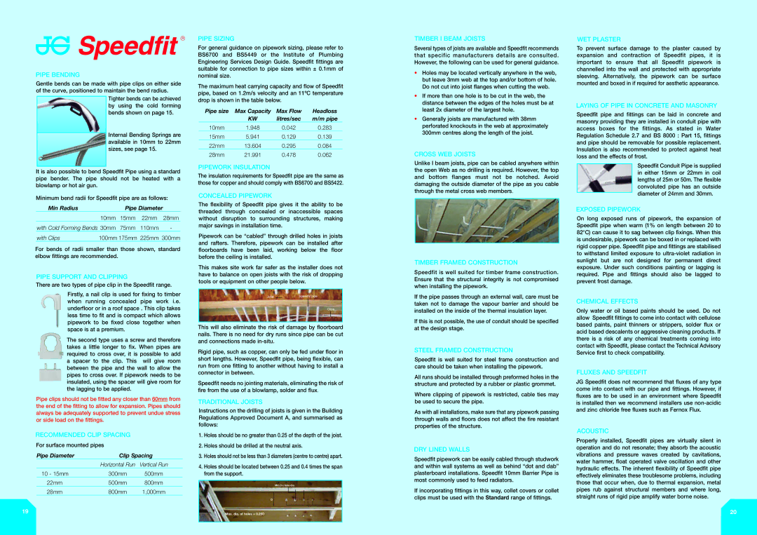
PIPE BENDING
Gentle bends can be made with pipe clips on either side of the curve, positioned to maintain the bend radius.
Tighter bends can be achieved by using the cold forming bends shown on page 15.
Internal Bending Springs are available in 10mm to 22mm sizes, see page 15.
It is also possible to bend Speedfit Pipe using a standard pipe bender. The pipe should not be heated with a blowlamp or hot air gun.
Minimum bend radii for Speedfit pipe are as follows:
Min Radius | | Pipe Diameter | |
| 10mm | 15mm | 22mm | 28mm |
with Cold Forming Bends 30mm | 75mm | 110mm | - |
with Clips | 100mm 175mm | 225mm 300mm |
For bends of radii smaller than those shown, standard elbow fittings are recommended.
PIPE SUPPORT AND CLIPPING
There are two types of pipe clip in the Speedfit range.
Firstly, a nail clip is used for fixing to timber when running concealed pipe work i.e. underfloor or in a roof space . This clip takes less time to fit and is compact which allows pipework to be fixed close together when space is at a premium.
The second type uses a screw and therefore takes a little longer to fix. When pipes are required to cross over, it is possible to add a spacer to the clip. This will give room between the pipe and the wall to allow the pipes to cross over. If pipework needs to be insulated, using the spacer will give room for the lagging to be applied.
Pipe clips should not be fitted any closer than 60mm from the end of the fitting to allow for expansion. Pipes should always be adequately supported to prevent undue stress or side load on the fittings.
RECOMMENDED CLIP SPACING
For surface mounted pipes
Pipe Diameter | Clip Spacing |
| Horizontal Run | Vertical Run |
10 - 15mm | 300mm | 500mm |
22mm | 500mm | 800mm |
28mm | 800mm | 1,000mm |
19
PIPE SIZING
For general guidance on pipework sizing, please refer to BS6700 and BS5449 or the Institute of Plumbing Engineering Services Design Guide. Speedfit fittings are suitable for connection to pipe sizes within ± 0.1mm of nominal size.
The maximum heat carrying capacity and flow of Speedfit pipe, based on 1.2m/s velocity and an 11ºC temperature drop is shown in the table below.
Pipe size | Max Capacity | Max Flow | Headloss |
| KW | litres/sec | m/m pipe |
10mm | 1.948 | 0.042 | 0.283 |
15mm | 5.941 | 0.129 | 0.139 |
22mm | 13.604 | 0.295 | 0.084 |
28mm | 21.991 | 0.478 | 0.062 |
PIPEWORK INSULATION
The insulation requirements for Speedfit pipe are the same as those for copper and should comply with BS6700 and BS5422.
CONCEALED PIPEWORK
The flexibility of Speedfit pipe gives it the ability to be threaded through concealed or inaccessible spaces without disruption to surrounding structures, making major savings in installation time.
Pipework can be “cabled” through drilled holes in joists and rafters. Therefore, pipework can be installed after floorboards have been laid, working below the floor before the ceiling is installed.
This makes site work far safer as the installer does not have to balance on open joists with the risk of dropping tools or equipment on other people below.
Clips
This will also eliminate the risk of damage by floorboard nails. There is no need for dry runs since pipe can be cut and connections made in-situ.
Rigid pipe, such as copper, can only be fed under floor in short lengths. However, Speedfit pipe, being flexible, can run from one fitting to another without having to install a connector in between.
Speedfit needs no jointing materials, eliminating the risk of fire from the use of a blowlamp, solder and flux.
TRADITIONAL JOISTS
Instructions on the drilling of joists is given in the Building Regulations Approved Document A, and summarised as follows:
1.Holes should be no greater than 0.25 of the depth of the joist.
2.Holes should be drilled at the neutral axis.
3.Holes should not be less than 3 diameters (centre to centre) apart.
4.Holes should be located between 0.25 and 0.4 times the span from the support.
Min 3 x hole dia.
D
Max. dia. of holes = 0.25D
TIMBER I BEAM JOISTS
Several types of joists are available and Speedfit recommends that specific manufacturers details are consulted. However, the following can be used for general guidance.
•Holes may be located vertically anywhere in the web, but leave 3mm web at the top and/or bottom of hole. Do not cut into joist flanges when cutting the web.
•If more than one hole is to be cut in the web, the distance between the edges of the holes must be at least 2x diameter of the largest hole.
•Generally joists are manufactured with 38mm perforated knockouts in the web at approximately 300mm centres along the length of the joist.
CROSS WEB JOISTS
Unlike I beam joists, pipe can be cabled anywhere within the open Web as no drilling is required. However, the top and bottom flanges must not be notched. Avoid damaging the outside diameter of the pipe as you cable through the metal cross web members.
TIMBER FRAMED CONSTRUCTION
Speedfit is well suited for timber frame construction. Ensure that the structural integrity is not compromised when installing the pipework.
If the pipe passes through an external wall, care must be taken not to damage the vapour barrier and should be installed on the inside of the thermal insulation layer.
If this is not possible, the use of conduit should be specified at the design stage.
STEEL FRAMED CONSTRUCTION
Speedfit is well suited for steel frame construction and care should be taken when installing the pipework.
All runs should be installed through preformed holes in the structure and protected by a rubber or plastic grommet.
Where clipping of pipework is restricted, cable ties may be used to secure the pipe.
As with all installations, make sure that any pipework passing through walls and floors does not affect the fire resistant properties of the structure.
DRY LINED WALLS
Speedfit pipework can be easily cabled through studwork and within wall systems as well as behind “dot and dab” plasterboard installations. Speedfit 10mm Barrier Pipe is most commonly used to feed radiators.
If incorporating fittings in this way, collet covers or collet clips must be used with the Standard range of fittings.
WET PLASTER
To prevent surface damage to the plaster caused by expansion and contraction of Speedfit pipes, it is important to ensure that all Speedfit pipework is channelled into the wall and protected with appropriate sleeving. Alternatively, the pipework can be surface mounted and boxed in if required for aesthetic appearance.
LAYING OF PIPE IN CONCRETE AND MASONRY
Speedfit pipe and fittings can be laid in concrete and masonry providing they are installed in conduit pipe with access boxes for the fittings. As stated in Water Regulation Schedule 2.7 and BS 8000 : Part 15, fittings and pipe should be removable for possible replacement. Insulation is also recommended to protect against heat loss and the effects of frost.
Speedfit Conduit Pipe is supplied in either 15mm or 22mm in coil lengths of 25m or 50m. The flexible convoluted pipe has an outside diameter of 24mm and 30mm.
EXPOSED PIPEWORK
On long exposed runs of pipework, the expansion of Speedfit pipe when warm (1% on length between 20 to 82°C) can cause it to sag between clip fixings. When this is undesirable, pipework can be boxed in or replaced with rigid copper pipe. Speedfit pipe and fittings are stabilised to withstand limited exposure to ultra-violet radiation in sunlight but are not designed for permanent direct exposure. Under such conditions painting or lagging is required. Pipe and fittings should also be lagged to prevent frost damage.
CHEMICAL EFFECTS
Only water or oil based paints should be used. Do not allow Speedfit fittings to come into contact with cellulose based paints, paint thinners or strippers, solder flux or acid based descalents or aggressive cleaning products. If there is a risk of any chemical treatments coming into contact with Speedfit, please contact the Technical Advisory Service first to check compatibility.
FLUXES AND SPEEDFIT
JG Speedfit does not recommend that fluxes of any type come into contact with our pipe and fittings. However, if fluxes are to be used in an environment where Speedfit is installed then we recommend installers use non-acidic and zinc chloride free fluxes such as Fernox Flux.
ACOUSTIC
Properly installed, Speedfit pipes are virtually silent in operation and do not resonate; they absorb the acoustic vibrations and pressure waves created by cavitations, water hammer, float operated valve oscillation and other hydraulic effects. The inherent flexibility of Speedfit pipe effectively eliminates these troublesome problems, including those that occur when, due to thermal expansion, metal pipes rub against structural members and where long, straight runs of rigid pipe amplify water borne noise.
20