562156-UIM-A-0610

FIELD CONNECTIONS POWER WIRING

1.Install the proper size weatherproof disconnect switch outdoors and within sight of the unit.

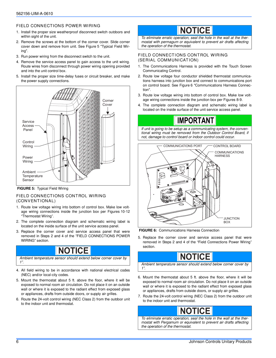
2.Remove the screws at the bottom of the corner cover. Slide corner cover down and remove from unit. See Figure 5 "Typical Field Wir- ing".

3.Run power wiring from the disconnect switch to the unit.

4.Remove the service access panel to gain access to the unit wiring. Route wires from disconnect through power wiring opening provided and into the unit control box.

5.Install the proper size time-delay fuses or circuit breaker, and make the power supply connections.

Corner

Cover

Service

Access

Panel

Control

Wiring

Power

Wiring

Ambient

Temperature

Sensor

FIGURE 5: Typical Field Wiring

FIELD CONNECTIONS CONTROL WIRING (CONVENTIONAL)

1.Route low voltage wiring into bottom of control box. Make low volt- age wiring connections inside the junction box per Figures 10-12 “Thermostat Wiring”.

2.The complete connection diagram and schematic wiring label is located on the inside surface of the unit service access panel.

3.Replace the corner cover and service access panel that were removed in Steps 2 and 4 of the ”FIELD CONNECTIONS POWER WIRING” section.

NOTICE

Ambient temperature sensor should extend below corner cover by 1”.

4.All field wiring to be in accordance with national electrical codes (NEC) and/or local-city codes.

5.Mount the thermostat about 5 ft. above the floor, where it will be exposed to normal room air circulation. Do not place it on an outside wall or where it is exposed to the radiant effect from exposed glass or appliances, drafts from outside doors, or supply air grilles.

6.Route the 24-volt control wiring (NEC Class 2) from the outdoor unit to the indoor unit and thermostat.

NOTICE

To eliminate erratic operation, seal the hole in the wall at the ther- mostat with permagum or equivalent to prevent air drafts affecting the operation of the thermostat.

FIELD CONNECTIONS CONTROL WIRING (SERIAL COMMUNICATION)

1.The Communications Harness is provided with the Touch Screen Communicating Control.

2.Route low voltage four conductor shielded thermostat communica- tions harness into junction box and connect to communications port on control board. See Figure 6 "Communications Harness Connec- tion".

3.Route low voltage wiring into bottom of control box. Make low volt- age wiring connections inside the junction box per Figures 8-9.

4.The complete connection diagram and schematic wiring label is located on the inside surface of the unit service access panel.

If unit is going to be setup as a communicating system, the conven- tional wiring must be removed from the Outdoor Control Board, if not, damage to control board or indoor control could occur.

COMMUNICATIONS PORT

CONTROL BOARD


COMMUNICATIONS


HARNESS


JUNCTION


BOX

FIGURE 6: Communications Harness Connection

5.Replace the corner cover and service access panel that were removed in Steps 2 and 4 of the “Field Connections Power Wiring” section.

NOTICE

Ambient temperature sensor should extend below corner cover by 1”.

6.Mount the thermostat about 5 ft. above the floor, where it will be exposed to normal room air circulation. Do not place it on an outside wall or where it is exposed to the radiant effect from exposed glass or appliances, drafts from outside doors, or supply air grilles.

7.Route the 24-volt control wiring (NEC Class 2) from the outdoor unit to the indoor unit and thermostat.

NOTICE

To eliminate erratic operation, seal the hole in the wall at the ther- mostat with Pergamum or equivalent to prevent air drafts affecting the operation of the thermostat.

6

Johnson Controls Unitary Products

Page 6
Image 6
Johnson Controls 16 SEER - CZF, AC6B Field Connections Power Wiring, Field Connections Control Wiring Conventional

AL6B SERIES, AC6B, 16 SEER - CZF specifications

The Johnson Controls AC6B, AL6B Series air conditioning units are designed to deliver efficient cooling solutions for residential and commercial applications. Known for their advanced technology and superior performance, these units comply with the latest standards in energy efficiency, boasting a 16 SEER (Seasonal Energy Efficiency Ratio) rating. This high rating indicates that these air conditioning systems consume less power while delivering optimum cooling, leading to significant cost savings on energy bills.

One of the standout features of the AC6B, AL6B Series is their variable-speed compressor technology. This allows the unit to adjust its cooling output in response to the specific demands of the environment, ensuring consistent temperatures while minimizing energy consumption. The variable-speed operation helps reduce wear and tear on the system, increasing longevity and reliability.

Another key characteristic of these units is their eco-friendly refrigerant, which contributes to lower environmental impact. The AC6B, AL6B Series utilize advanced heat exchanger designs that enhance heat transfer efficiency, further optimizing cooling performance while reducing energy usage.

Designed with user comfort in mind, these systems come equipped with advanced dehumidification capabilities, effectively managing indoor humidity levels. This ensures a more comfortable living or working environment, especially in humid climates.

In addition to performance, installation and maintenance are simplified with the AC6B, AL6B Series. The units are engineered for ease of installation, featuring lightweight components that reduce labor costs. Maintenance is also straightforward, with accessible service panels and clear maintenance guidelines, offering further convenience for homeowners and facility managers alike.

The aesthetic design of the AC6B, AL6B Series blends seamlessly into various architectural styles, making them an attractive choice for both new constructions and retrofits. The robust construction quality ensures durability, suitable for varying weather conditions.

Overall, the Johnson Controls AC6B, AL6B Series air conditioning units present a comprehensive solution for those seeking energy-efficient, reliable, and user-friendly cooling systems. With their multitude of features and advanced technology, they stand as a robust option for enhancing indoor comfort while minimizing environmental impact.