FURNACE LOCATION AND CLEARANCES
The furnace shall be located using the following guidelines:
1.Where a minimum amount of air intake/vent piping and elbows will be required.
2.As centralized with the air distribution as possible.
3.Where adequate combustion air will be available (particularly when the appliance is not using outdoor combustion air).
4.Where it will not interfere with proper air circulation in the confined space.
5.Where the outdoor vent terminal will not be blocked or restricted. Refer to “VENT CLEARANCES” located in SECTION VII of these instructions. These minimum clearances must be maintained in the installation.
6.Where the unit will be installed in a level position with no more than 1/4” (6.4 mm) slope side-to-side and front-to-back to provide proper condensate drainage.
Installation in freezing temperatures:
1.Furnace shall be installed in an area where ventilation facilities provide for safe limits of ambient temperature under normal oper- ating conditions. Ambient temperatures must not fall below 32°F (0°C) unless the condensate system is protected from freezing.
Improper installation in an ambient below 32ºF (0.0° C) could create a hazard, resulting in damage, injury or death.
2.Do not allow return air temperature to be below 55º F (13° C) for extended periods. To do so may cause condensation to occur in the main heat exchanger, leading to premature heat exchanger failure.
3.If this furnace is installed in an unconditioned space and an extended power failure occurs, there will be potential damage to the internal components. Following a power failure situation, do not operate the unit until inspection and repairs are performed.
4.Special precautions MUST be made if installing furnace in an area which may drop below freezing. This can cause improper opera- tion or damage to the equipment. If the furnace is installed in an area that has the potential of freezing, the drain line must be pro- tected. Use a 3 to 6 watt per foot at 115 vac, 40º F (4.4° C) self- regulating, shielded and waterproof heat tape. Wrap the drain line outside of the furnace with the heat tape and secure with ties. Fol- low the heat tape manufacturer's recommendations.
Use only Propylene Glycol (RV anti-freeze) to winterize the furnace. Refer to the manufacturer’s specification to ensure that it is compat- ible with plastics and other components of the furnace. DO NOT use Ethylene Glycol anti-freeze in the furnace.
Clearances for access/service:
Ample clearances should be provided to permit easy access to the unit. The following minimum clearances are recommended:
1.Twenty-four (24) inches (61 cm) between the front of the furnace and an adjacent wall or another appliance, when access is required for servicing and cleaning.
2.Eighteen (18) inches (46 cm) at the side where access is required for passage to the front when servicing or for inspection or replace- ment of flue/vent connections.
In all cases, accessibility clearances shall take precedence over clear- ances for combustible materials where accessibility clearances are greater.
Installation in a residential garage:
A gas-fired furnace for installation in a residential garage must be installed so the burner(s) and the ignition source are located not less than 18 inches (46 cm) above the floor, and the furnace must be located or protected to avoid physical damage by vehicles.
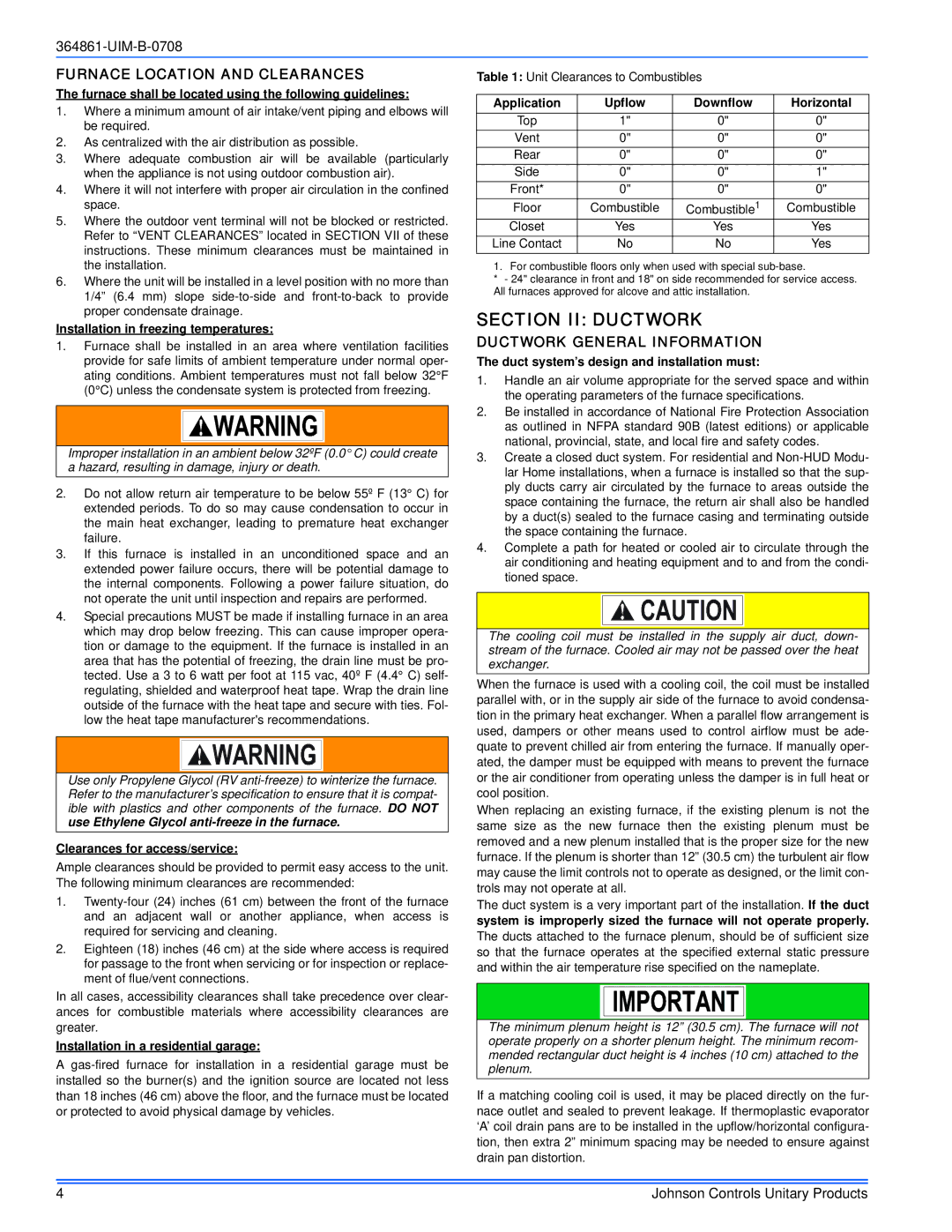
Table 1: Unit Clearances to Combustibles
Application | Upflow | Downflow | Horizontal |
Top | 1" | 0" | 0" |
Vent | 0" | 0" | 0" |
Rear | 0" | 0" | 0" |
Side | 0" | 0" | 1" |
Front* | 0" | 0" | 0" |
Floor | Combustible | Combustible1 | Combustible |
Closet | Yes | Yes | Yes |
Line Contact | No | No | Yes |
1. For combustible floors only when used with special sub-base.
*- 24" clearance in front and 18" on side recommended for service access. All furnaces approved for alcove and attic installation.
SECTION II: DUCTWORK
DUCTWORK GENERAL INFORMATION
The duct system’s design and installation must:
1.Handle an air volume appropriate for the served space and within the operating parameters of the furnace specifications.
2.Be installed in accordance of National Fire Protection Association as outlined in NFPA standard 90B (latest editions) or applicable national, provincial, state, and local fire and safety codes.
3.Create a closed duct system. For residential and Non-HUD Modu- lar Home installations, when a furnace is installed so that the sup- ply ducts carry air circulated by the furnace to areas outside the space containing the furnace, the return air shall also be handled by a duct(s) sealed to the furnace casing and terminating outside the space containing the furnace.
4.Complete a path for heated or cooled air to circulate through the air conditioning and heating equipment and to and from the condi- tioned space.
The cooling coil must be installed in the supply air duct, down- stream of the furnace. Cooled air may not be passed over the heat exchanger.
When the furnace is used with a cooling coil, the coil must be installed parallel with, or in the supply air side of the furnace to avoid condensa- tion in the primary heat exchanger. When a parallel flow arrangement is used, dampers or other means used to control airflow must be ade- quate to prevent chilled air from entering the furnace. If manually oper- ated, the damper must be equipped with means to prevent the furnace or the air conditioner from operating unless the damper is in full heat or cool position.
When replacing an existing furnace, if the existing plenum is not the same size as the new furnace then the existing plenum must be removed and a new plenum installed that is the proper size for the new furnace. If the plenum is shorter than 12” (30.5 cm) the turbulent air flow may cause the limit controls not to operate as designed, or the limit con- trols may not operate at all.
The duct system is a very important part of the installation. If the duct system is improperly sized the furnace will not operate properly.
The ducts attached to the furnace plenum, should be of sufficient size so that the furnace operates at the specified external static pressure and within the air temperature rise specified on the nameplate.
The minimum plenum height is 12” (30.5 cm). The furnace will not operate properly on a shorter plenum height. The minimum recom- mended rectangular duct height is 4 inches (10 cm) attached to the plenum.
If a matching cooling coil is used, it may be placed directly on the fur- nace outlet and sealed to prevent leakage. If thermoplastic evaporator ‘A’ coil drain pans are to be installed in the upflow/horizontal configura- tion, then extra 2” minimum spacing may be needed to ensure against drain pan distortion.