364861-UIM-B-0708

COIL FLANGE INSTALLATION

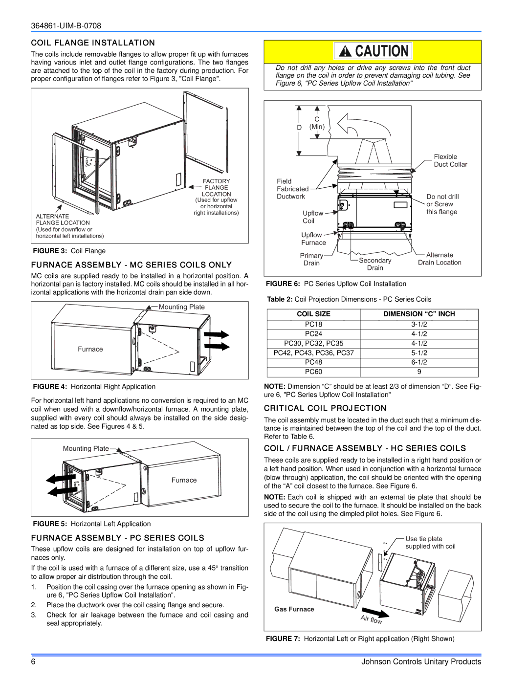
The coils include removable flanges to allow proper fit up with furnaces having various inlet and outlet flange configurations. The two flanges are attached to the top of the coil in the factory during production. For proper configuration of flanges refer to Figure 3, "Coil Flange".

Do not drill any holes or drive any screws into the front duct flange on the coil in order to prevent damaging coil tubing. See Figure 6, "PC Series Upflow Coil Installation"

ALTERNATE FLANGE LOCATION (Used for downflow or horizontal left installations)

FACTORY

FLANGE

LOCATION

(Used for upflow

or horizontal

right installations)

C

D(Min)


Flexible


Duct Collar

Field


Fabricated


Ductwork

Do not drill


or Screw

Upflow

this flange

Coil


Upflow


Furnace


FIGURE 3: Coil Flange

FURNACE ASSEMBLY - MC SERIES COILS ONLY

MC coils are supplied ready to be installed in a horizontal position. A horizontal pan is factory installed. MC coils should be installed in all hor- izontal applications with the horizontal drain pan side down.

Mounting Plate

Furnace

FIGURE 4: Horizontal Right Application

For horizontal left hand applications no conversion is required to an MC coil when used with a downflow/horizontal furnace. A mounting plate, supplied with every coil should always be installed on the side desig- nated as top side. See Figures 4 & 5.

Mounting Plate

Furnace

FIGURE 5: Horizontal Left Application

FURNACE ASSEMBLY - PC SERIES COILS

These upflow coils are designed for installation on top of upflow fur- naces only.

If the coil is used with a furnace of a different size, use a 45° transition to allow proper air distribution through the coil.

1.Position the coil casing over the furnace opening as shown in Fig- ure 6, "PC Series Upflow Coil Installation".

2.Place the ductwork over the coil casing flange and secure.

3.Check for air leakage between the furnace and coil casing and seal appropriately.

Primary

Secondary

Alternate

Drain

Drain Location

Drain


FIGURE 6: PC Series Upflow Coil Installation

Table 2: Coil Projection Dimensions - PC Series Coils

COIL SIZE

DIMENSION “C” INCH

PC18

3-1/2

PC24

4-1/2

PC30, PC32, PC35

4-1/2

PC42, PC43, PC36, PC37

5-1/2

PC48

6-1/2

PC60

9

NOTE: Dimension “C” should be at least 2/3 of dimension “D”. See Fig- ure 6, "PC Series Upflow Coil Installation"

CRITICAL COIL PROJECTION

The coil assembly must be located in the duct such that a minimum dis- tance is maintained between the top of the coil and the top of the duct. Refer to Table 6.

COIL / FURNACE ASSEMBLY - HC SERIES COILS

These coils are supplied ready to be installed in a right hand position or a left hand position. When used in conjunction with a horizontal furnace (blow through) application, the coil should be oriented with the opening of the “A” coil closest to the furnace. See Figure 6.

NOTE: Each coil is shipped with an external tie plate that should be used to secure the coil to the furnace. It should be installed on the back side of the coil using the dimpled pilot holes. See Figure 6.

Use tie plate

supplied with coil

Gas Furnace

FIGURE 7: Horizontal Left or Right application (Right Shown)

6

Johnson Controls Unitary Products

Page 6
Image 6
Johnson Controls TG9S*MP Coil Flange Installation, Furnace Assembly MC Series Coils only, Furnace Assembly PC Series Coils

TG9S*MP, GG9S*MP specifications

Johnson Controls has long been at the forefront of building efficiency solutions, and their TG9S*MP and GG9S*MP series exemplify this commitment. These two-stage, multi-position gas furnaces are designed for optimal comfort and performance in residential applications, and they come packed with a variety of features that enhance their efficiency and operational capabilities.

One of the standout features of the TG9S*MP and GG9S*MP furnaces is their efficient two-stage operation. This technology allows the unit to operate at a lower capacity most of the time, which translates into reduced energy consumption and costs. When the demand for heating increases, the furnace automatically shifts to a higher capacity, ensuring a consistent and comfortable indoor temperature. This flexibility not only enhances comfort but also extends the lifespan of the unit as it doesn't have to work harder than necessary.

Energy efficiency is a crucial characteristic of both models. With an Annual Fuel Utilization Efficiency (AFUE) rating of up to 96%, these furnaces convert a significant amount of the fuel they consume into usable heat. Such efficiency ratings not only help in reducing energy bills but also have a positive impact on the environment by minimizing greenhouse gas emissions.

Both models feature advanced technology in their design, including a fully modulating gas valve and a variable-speed blower motor. The modulating valve adjusts the gas flow in response to the thermostat’s signals, allowing for precise temperature control and improved comfort. Meanwhile, the variable-speed blower motor enhances airflow while operating quietly, significantly improving overall indoor air quality by promoting even heat distribution throughout the home.

From a structural standpoint, the TG9S*MP and GG9S*MP are built with durable materials designed for longevity. Their compact design allows for flexible installation options, whether in a closet, attic, or basement. The furnaces also come equipped with a robust heat exchanger crafted from high-quality materials, which ensures both reliability and efficiency.

In conclusion, the Johnson Controls TG9S*MP and GG9S*MP furnaces provide homeowners with efficient, reliable, and comfortable heating solutions. With advanced features such as two-stage operation, impressive AFUE ratings, and modern technology integrations, these models stand out in the market as dependable options for both energy savings and year-round comfort. Whether you're a homeowner looking to upgrade your heating system or a contractor seeking high-quality products for your clients, these furnaces represent a smart choice.