356485-UIM-G-1211


LEFT SIDE

Vent Connection


Outlet


Electrical


Entry


Gas Pipe


Entry


Thermostat


Wiring


28.5”


29.5”


4” Diameter

.5”

24.38”

Vent Connection

Outlet


B


C

.5”

20”


FRONT

A

RIGHT SIDE


Electrical


Entry


Vent


Connection


Outlet


Gas Pipe


Entry


33”


23”


Thermostat


Wiring


14”

1.5”

1”

.5”


.5”

B


24.25”


SUPPLY END


RETURN END


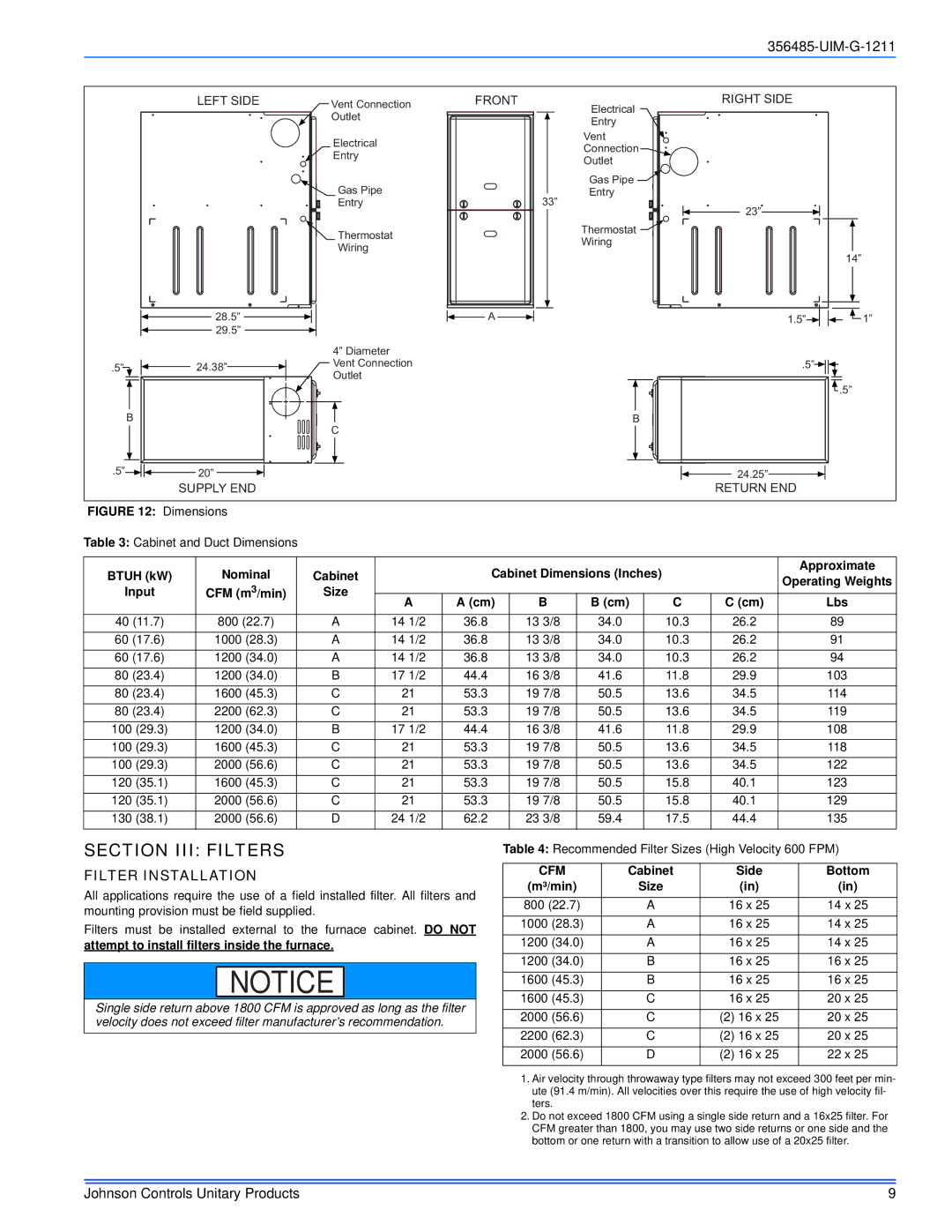
FIGURE 12: Dimensions


Table 3: Cabinet and Duct Dimensions


BTUH (kW)


Nominal


Cabinet


Cabinet Dimensions (Inches)


Approximate


Operating Weights

Input


CFM (m3/min)


Size


A

A (cm)

B

B (cm)


C

C (cm)

Lbs


40 (11.7)


800 (22.7)


A

14 1/2

36.8

13 3/8

34.0


10.3

26.2

89

60 (17.6)


1000 (28.3)


A

14 1/2

36.8

13 3/8

34.0


10.3

26.2

91

60 (17.6)


1200 (34.0)


A

14 1/2

36.8

13 3/8

34.0


10.3

26.2

94

80 (23.4)


1200 (34.0)


B

17 1/2

44.4

16 3/8

41.6


11.8

29.9

103

80 (23.4)


1600 (45.3)


C

21

53.3

19 7/8

50.5


13.6

34.5

114

80 (23.4)


2200 (62.3)


C

21

53.3

19 7/8

50.5


13.6

34.5

119

100 (29.3)


1200 (34.0)


B

17 1/2

44.4

16 3/8

41.6


11.8

29.9

108

100 (29.3)


1600 (45.3)


C

21

53.3

19 7/8

50.5


13.6

34.5

118

100 (29.3)


2000 (56.6)


C

21

53.3

19 7/8

50.5


13.6

34.5

122

120 (35.1)


1600 (45.3)


C

21

53.3

19 7/8

50.5


15.8

40.1

123

120 (35.1)


2000 (56.6)


C

21

53.3

19 7/8

50.5


15.8

40.1

129

130 (38.1)


2000 (56.6)


D

24 1/2

62.2

23 3/8

59.4


17.5

44.4

135

SECTION III: FILTERS

FILTER INSTALLATION

All applications require the use of a field installed filter. All filters and mounting provision must be field supplied.

Filters must be installed external to the furnace cabinet. DO NOT

attempt to install filters inside the furnace.

NOTICE

Single side return above 1800 CFM is approved as long as the filter velocity does not exceed filter manufacturer’s recommendation.

Table 4: Recommended Filter Sizes (High Velocity 600 FPM)

CFM

Cabinet

Side

Bottom

(m³/min)

Size

(in)

(in)

800 (22.7)

A

16 x 25

14 x 25

1000 (28.3)

A

16 x 25

14 x 25

1200 (34.0)

A

16 x 25

14 x 25

1200 (34.0)

B

16 x 25

16 x 25

1600 (45.3)

B

16 x 25

16 x 25

1600 (45.3)

C

16 x 25

20 x 25

2000 (56.6)

C

(2) 16 x 25

20 x 25

2200 (62.3)

C

(2) 16 x 25

20 x 25

2000 (56.6)

D

(2) 16 x 25

22 x 25

1.Air velocity through throwaway type filters may not exceed 300 feet per min- ute (91.4 m/min). All velocities over this require the use of high velocity fil- ters.

2.Do not exceed 1800 CFM using a single side return and a 16x25 filter. For CFM greater than 1800, you may use two side returns or one side and the bottom or one return with a transition to allow use of a 20x25 filter.

Johnson Controls Unitary Products

9

Page 9
Image 9
Johnson Controls TG8S*MP Section III Filters, Filter Installation, Btuh kW, Attempt to install filters inside the furnace

TG8S*MP, GG8S*MP, TGLS*MP, GGLS*MP specifications

Johnson Controls is a leader in the development of innovative building management solutions, and its product line encompassing the GGLS*MP, TGLS*MP, TG8S*MP, and GG8S*MP series exemplifies this commitment to excellence. These devices are designed to optimize energy efficiency, enhance occupant comfort, and ensure seamless integration into commercial building infrastructures.

The GGLS*MP series focuses on the integration of advanced sensors and controllers that facilitate effective lighting and HVAC management. With built-in capabilities for occupancy sensing and daylight harvesting, these devices can automatically adjust settings based on real-time conditions. Their energy-efficient operation not only contributes to lower utility costs but also supports sustainability goals, making them ideal for modern green buildings.

In contrast, the TGLS*MP series emphasizes the importance of temperature regulation and comfort in residential or smaller commercial settings. These controllers utilize advanced algorithms to maintain optimal indoor climates, adjusting heating and cooling outputs in response to ambient conditions. The intuitive user interface makes it easy for users to customize their settings, providing enhanced comfort without sacrificing energy efficiency.

The TG8S*MP series is particularly renowned for its robust communication features. These devices support multiple communication protocols, allowing them to integrate smoothly with existing building management systems. This versatility ensures that customers can leverage their current infrastructure while benefiting from new technology. Additionally, the TG8S*MP includes remote monitoring capabilities, enabling facility managers to track performance metrics and troubleshoot issues from anywhere.

Lastly, the GG8S*MP series brings together security and control features, ensuring that buildings are not only energy-efficient but also secure. With capabilities for access control and monitoring, these devices provide a comprehensive solution for managing facility safety. Their integration with lighting and HVAC systems further enhances overall efficiency, creating a comfortable and secure environment for all occupants.

In summary, Johnson Controls’ GGLS*MP, TGLS*MP, TG8S*MP, and GG8S*MP series presents cutting-edge technologies designed for energy efficiency, ease of use, and versatility. By focusing on comprehensive building management, these products provide optimal performance that aligns with sustainability objectives while enhancing comfort and security. Whether in commercial or residential settings, Johnson Controls continues to lead the way in the intelligent building sector.