4/29/03
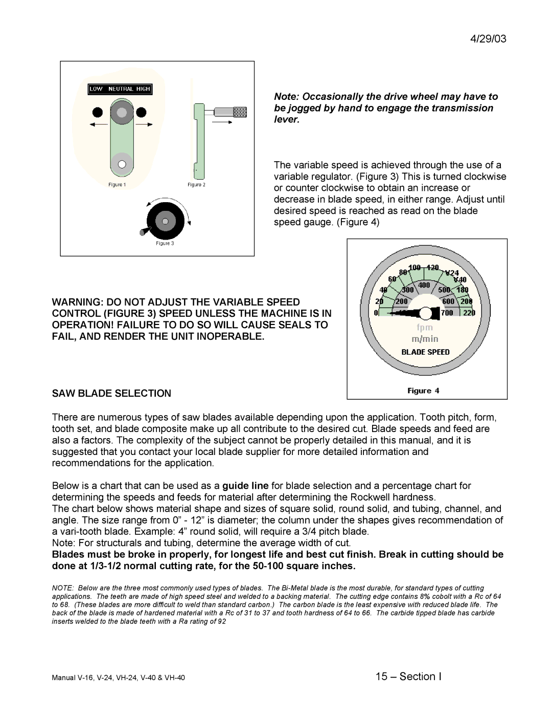
Note: Occasionally the drive wheel may have to be jogged by hand to engage the transmission lever.
The variable speed is achieved through the use of a variable regulator. (Figure 3) This is turned clockwise or counter clockwise to obtain an increase or decrease in blade speed, in either range. Adjust until desired speed is reached as read on the blade speed gauge. (Figure 4)
WARNING: DO NOT ADJUST THE VARIABLE SPEED
CONTROL (FIGURE 3) SPEED UNLESS THE MACHINE IS IN
OPERATION! FAILURE TO DO SO WILL CAUSE SEALS TO
FAIL, AND RENDER THE UNIT INOPERABLE.
SAW BLADE SELECTION
There are numerous types of saw blades available depending upon the application. Tooth pitch, form, tooth set, and blade composite make up all contribute to the desired cut. Blade speeds and feed are also a factors. The complexity of the subject cannot be properly detailed in this manual, and it is suggested that you contact your local blade supplier for more detailed information and recommendations for the application.
Below is a chart that can be used as a guide line for blade selection and a percentage chart for determining the speeds and feeds for material after determining the Rockwell hardness.
The chart below shows material shape and sizes of square solid, round solid, and tubing, channel, and angle. The size range from 0” - 12” is diameter; the column under the shapes gives recommendation of a
Note: For structurals and tubing, determine the average width of cut.
Blades must be broke in properly, for longest life and best cut finish. Break in cutting should be done at
NOTE: Below are the three most commonly used types of blades. The
Manual | 15 – Section I |
