4/29/03
HIGH SPEED ROLLER GUIDES
Applications and Advantages:
Friction and abrasive cutting, filing operations, aluminum and woodcutting.
These guides eliminate having to change inserts when changing to blades of different widths.
Requirements for Installation:
These roller guides must be installed using a new 1/2” blade width band for proper alignment. The 1/2” band should be tracked within the approximate center line of the band wheels.
Note: Be certain band wheels are clean are free of any foreign material build up before proceeding.
Tools / Hardware Required:
Drill - 7/16”
Drill and tap for ¼” 20 set screw ¼” 20 set screw 1/4 - 3/8” long
Upper Guide Installation:
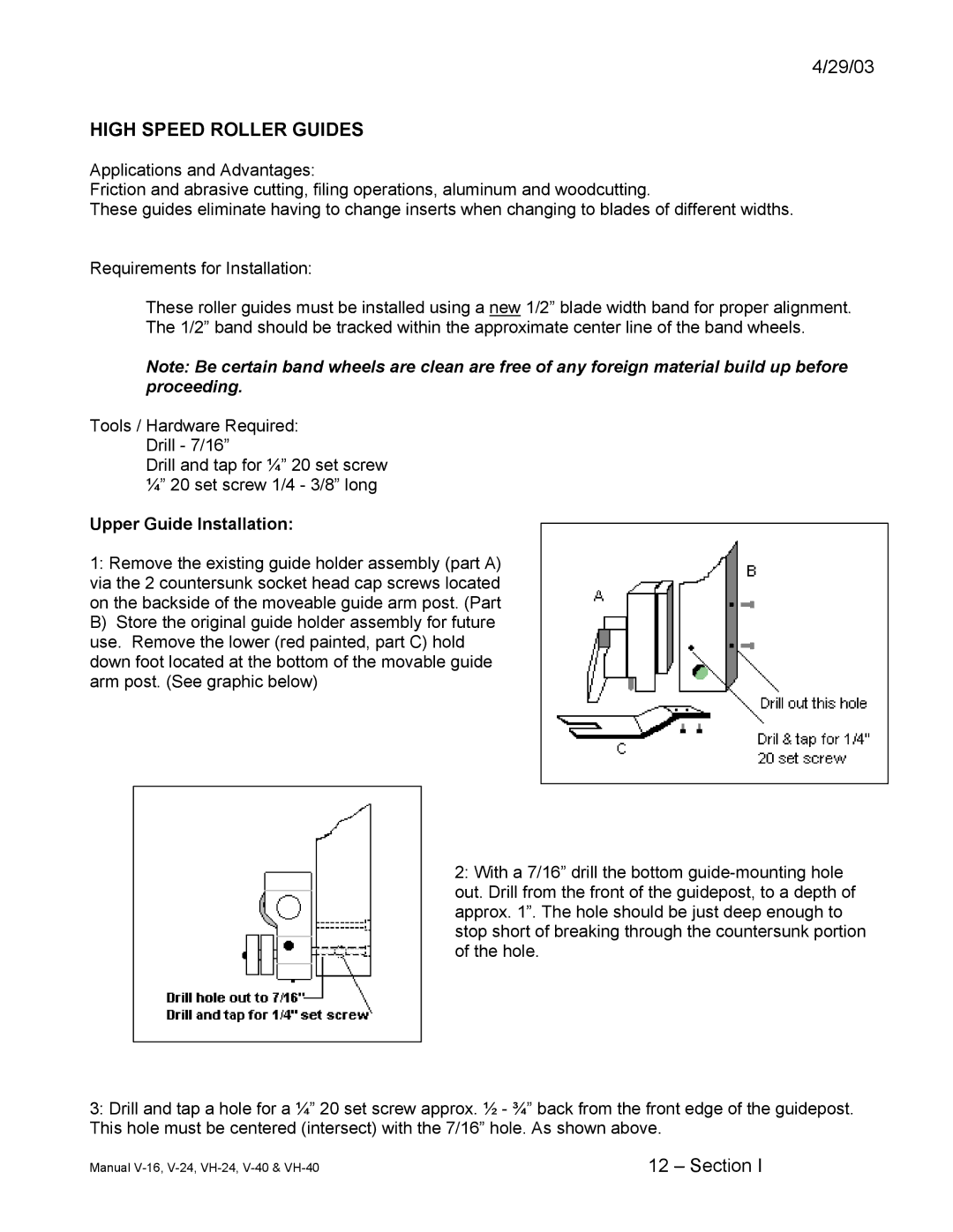
1:Remove the existing guide holder assembly (part A) via the 2 countersunk socket head cap screws located on the backside of the moveable guide arm post. (Part B) Store the original guide holder assembly for future use. Remove the lower (red painted, part C) hold down foot located at the bottom of the movable guide arm post. (See graphic below)
2:With a 7/16” drill the bottom
3:Drill and tap a hole for a ¼” 20 set screw approx. ½ - ¾” back from the front edge of the guidepost. This hole must be centered (intersect) with the 7/16” hole. As shown above.
Manual | 12 – Section I |
