MX240 and MX480 Ethernet Services Router Fan Tray Installation Instructions
Cooling System
The cooling system consists of the following components:
■Fan tray
■Air filter
The cooling system components work together to keep all router components within the acceptable temperature range (see Figure 1 on page 2, Figure 2 on page 2, Figure 3 on page 3, Figure 4 on page 3, Figure 5 on page 4, and
Figure 6 on page 4). The router has one fan tray and one air filter that install vertically in the rear of the router. The fan tray contains three fans on an MX240 router and six fans on an MX480 router.
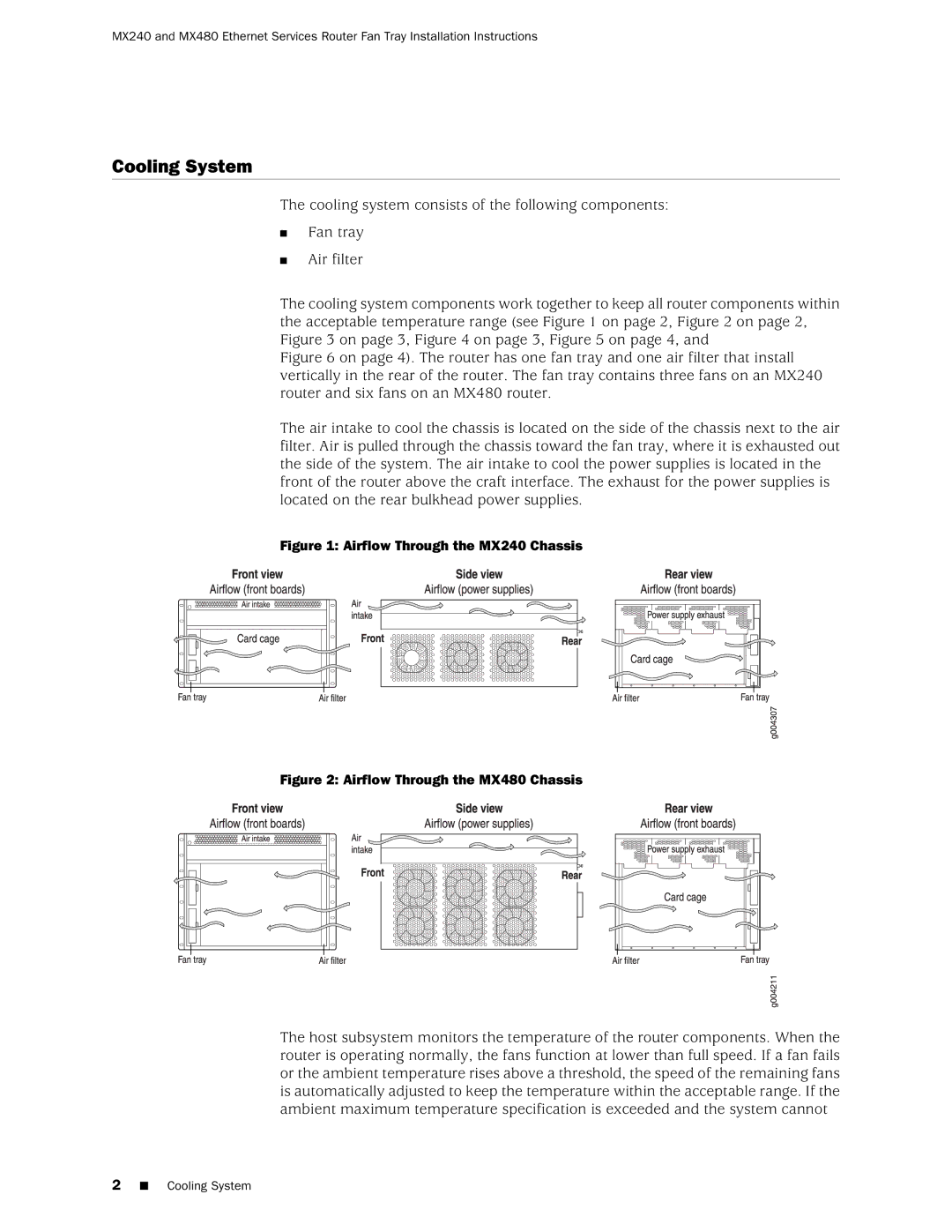
The air intake to cool the chassis is located on the side of the chassis next to the air filter. Air is pulled through the chassis toward the fan tray, where it is exhausted out the side of the system. The air intake to cool the power supplies is located in the front of the router above the craft interface. The exhaust for the power supplies is located on the rear bulkhead power supplies.
Figure 1: Airflow Through the MX240 Chassis
Figure 2: Airflow Through the MX480 Chassis
The host subsystem monitors the temperature of the router components. When the router is operating normally, the fans function at lower than full speed. If a fan fails or the ambient temperature rises above a threshold, the speed of the remaining fans is automatically adjusted to keep the temperature within the acceptable range. If the ambient maximum temperature specification is exceeded and the system cannot
2■ Cooling System