ADJUSTMENTS
B1 POWER SUPPLY
Item | Measuring | Test point | Ad justment part |
| Description |
instrument |
| ||||
|
|
|
|
| |
|
|
|
|
|
|
Check of | Signal |
| 1. | Input a whole black signal. | |
B1 Power | generator |
| 2. | Connect a DC voltmeter to | |
Supply |
|
| |||
|
|
| 3. | Make sure that the voltage is DC116.5±2.0V. | |
| DC Volt- |
|
| ||
|
|
|
|
| |
| meter |
|
|
|
|
|
|
|
|
|
|
FOCUS ADJUSTMENT
Item | Measuring | Test point | Ad justment part |
| Description |
instrument |
| ||||
|
|
|
|
| |
|
|
|
|
|
|
|
|
|
|
|
|
Ad justment | Signal |
| FOCUS VR | 1. | Input a |
of FOCUS | generator |
| [In HVT] | 2. | While watching the screen, adjust the FOCUS VR to make the |
|
|
| |||
|
|
|
|
| vertical and horizontal lines as fine and sharp as possible. |
|
|
|
| 3. | Make sure that when the screen is darkened, the lines remain in |
|
|
|
|
| good focus. |
|
|
|
|
|
|
IF CIRCUIT ADJUSTMENT
Item
Measuring instrument
Test point
Ad justment part
Description
Ad justment |
| Signal |
|
|
|
|
|
| 1. VCO | |||||
of VCO(CW) |
| generator |
|
|
|
|
|
|
|
|
| |||
|
|
|
| Remote |
|
|
|
|
|
|
|
|
| |
|
|
|
| control unit |
|
|
|
|
|
|
|
|
| |
|
|
|
|
|
|
|
|
|
|
|
|
|
| |
|
|
|
|
|
|
|
|
|
|
| ||||
|
|
|
|
|
|
|
|
|
|
|
| |||
|
|
| VCO (CW) ***.** MHz |
|
|
|
|
|
| |||||
|
|
|
|
|
|
|
|
|
|
|
|
|
| |
|
|
| TOO HIGH |
|
|
|
|
|
|
|
|
| ||
|
|
| ABOVE REFERENCE |
|
|
|
|
|
|
|
|
| ||
|
|
| JUST REFERENCE |
|
|
|
|
| YELLOW |
|
| |||
|
|
|
|
|
|
|
|
|
| |||||
|
|
| BELOW REFERENCE |
|
|
|
|
|
|
|
|
| ||
|
|
| TOO LOW |
|
|
|
|
|
|
|
|
| ||
|
|
| AFT ADJUST | ** *(* *) |
|
|
|
|
|
| ||||
|
|
| VCO ADJUST | ** *(* *) |
|
|
|
|
|
| ||||
|
|
| FINE |
|
|
|
|
|
| Do no t adjust | ||||
|
|
| DISP : EXIT |
|
| |||||||||
|
|
|
|
|
|
|
|
|
|
| ||||
|
|
|
|
|
|
|
|
|
|
|
|
|
|
|
TOO HIGH
ABOVE REFERENCE
![]()
![]() J US T R EFE RE NC E
J US T R EFE RE NC E![]()
![]() BELOW REFERENCE
BELOW REFERENCE
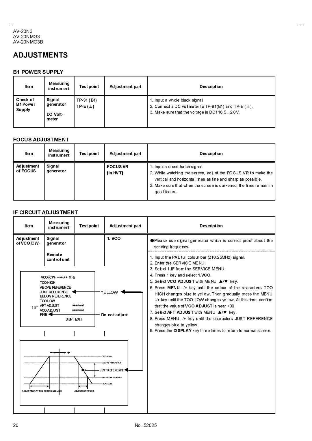
●Please use signal generator which is correct proof about the sending frequency.
1.Input the PAL full colour bar (210.25MHz) signal.
2.Enter the SERVICE MENU.
3.Select 1.IF from the SERVICE MENU.
4.Press 1 key and select 1.VCO.
5.Select VCO ADJUST with MENU ▲/▼ key.
6.Press MENU
HIGH changes blue to yellow. Then gradually press the MENU
7.Select AFT ADJUST with MENU ▲/▼ key.
8.Press MENU
9.Press the DISPLAY key three times to return to normal screen.
TOO LOW
ADJUSTMENT AT THIS POINT IS USELESS | ADJUSTMENT POINT |
20 | No. 52025 |