Connections
Connecting to an External Amplifier
| AUDIO | VIDEO | S VIDEO |
R | L MONO |
| OVER |
![]() INPUT 1
INPUT 1
|
|
| INPUT 2 | |
| INPUT 4 | COMPONENT | COMPONENT | |
AUDIO | ||||
VIDEO | VIDEO | |||
R | L MONO | |||
|
| |||
R | L |
| Y | |
AUDIO OUT |
| PB | ||
|
| |||
AV COMPULINK |
|
| PR | |
75Ω
(VHF / UHF)
LEFT FRONT | RIGHT FRONT |
SPEAKER | SPEAKER |
AMPLIFIER
Illustration of
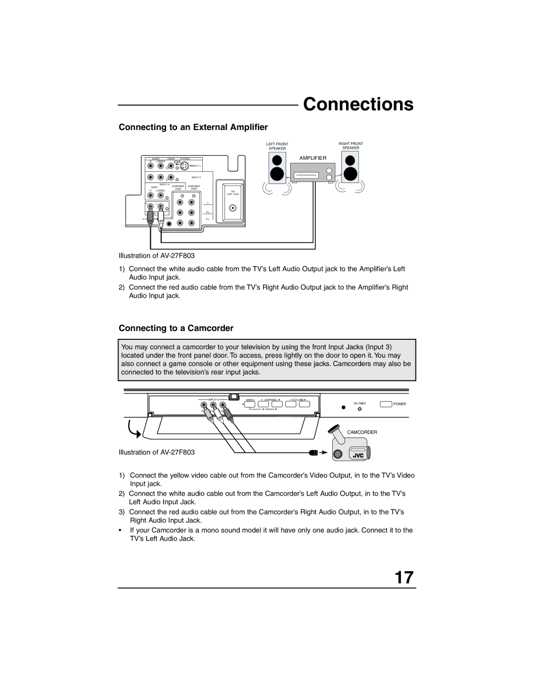
1)Connect the white audio cable from the TV’s Left Audio Output jack to the Amplifier’s Left Audio Input jack.
2)Connect the red audio cable from the TV’s Right Audio Output jack to the Amplifier’s Right Audio Input jack.
Connecting to a Camcorder
You may connect a camcorder to your television by using the front Input Jacks (Input 3) located under the front panel door. To access, press lightly on the door to open it. You may also connect a game console or other equipment using these jacks. Camcorders may also be connected to the television’s rear input jacks.
INPUT 3 | MENU | CHANNEL | VOLUME |
|
|
|
| ON TIMER | POWER |
|
| OPERATE |
|
|
CAMCORDER
Illustration of
1)Connect the yellow video cable out from the Camcorder’s Video Output, in to the TV’s Video Input jack.
2)Connect the white audio cable out from the Camcorder’s Left Audio Output, in to the TV’s Left Audio Input Jack.
3)Connect the red audio cable out from the Camcorder’s Right Audio Output, in to the TV’s Right Audio Input Jack.
•If your Camcorder is a mono sound model it will have only one audio jack. Connect it to the TV’s Left Audio Jack.
17
