Connections
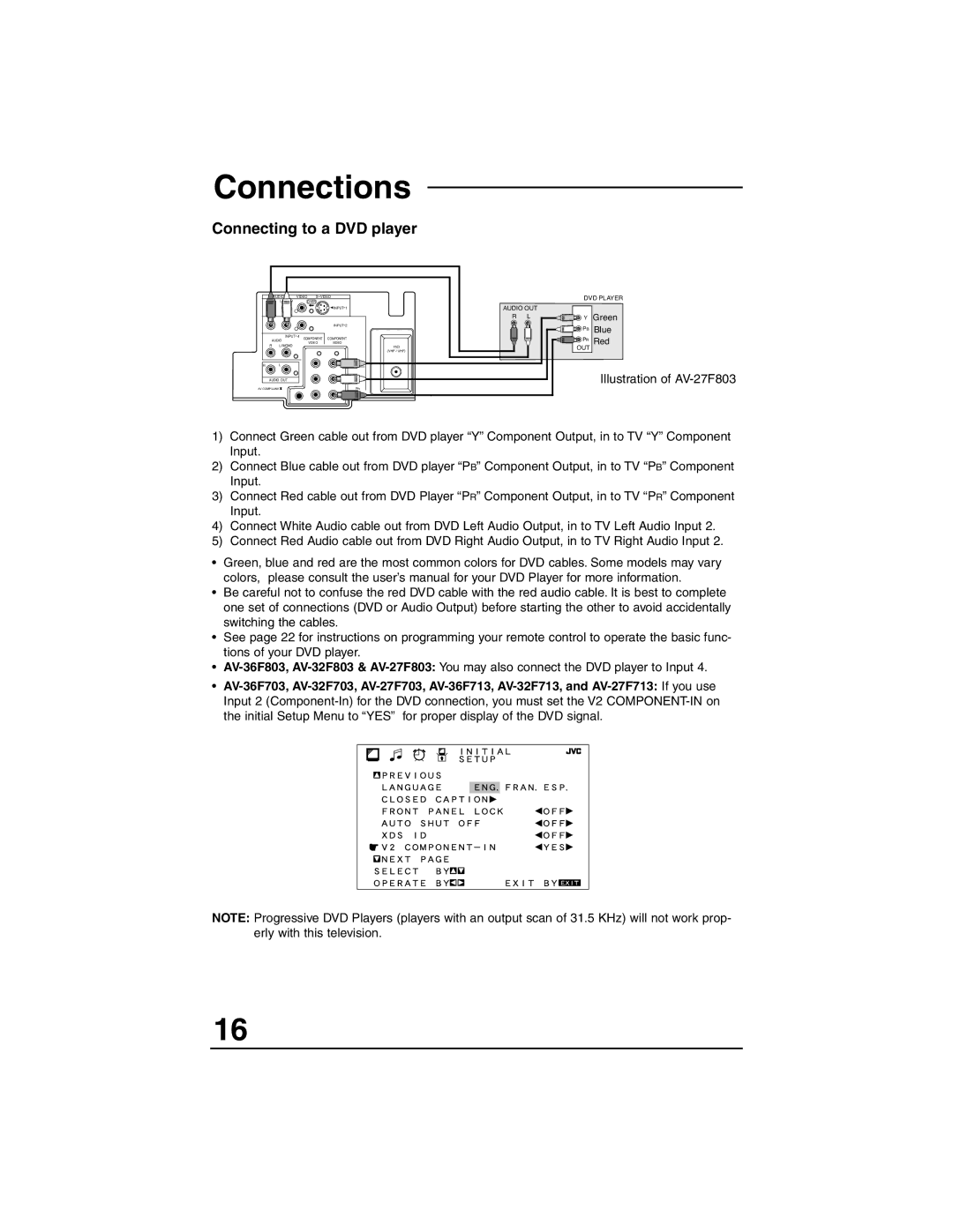
Connecting to a DVD player
| AUDIO | VIDEO | S VIDEO | |
R | L MONO |
| OVER |
|
|
|
|
| INPUT 1 |
|
|
|
| INPUT 2 |
| INPUT 4 |
| COMPONENT | |
AUDIO | COMPONENT | |||
R | L MONO |
| VIDEO | VIDEO |
|
| 75Ω | ||
|
|
|
| (VHF / UHF) |
R | L |
|
| Y |
AUDIO OUT |
|
| PB | |
AV COMPULINK |
|
| PR | |
DVD PLAYER
AUDIO OUT
RL ![]()
![]()
![]() Y Green
Y Green
![]()
![]()
![]() PB Blue
PB Blue
![]()
![]()
![]() PR Red
PR Red
OUT
Illustration of
1)Connect Green cable out from DVD player “Y” Component Output, in to TV “Y” Component Input.
2)Connect Blue cable out from DVD player “PB” Component Output, in to TV “PB” Component Input.
3)Connect Red cable out from DVD Player “PR” Component Output, in to TV “PR” Component Input.
4)Connect White Audio cable out from DVD Left Audio Output, in to TV Left Audio Input 2.
5)Connect Red Audio cable out from DVD Right Audio Output, in to TV Right Audio Input 2.
•Green, blue and red are the most common colors for DVD cables. Some models may vary colors, please consult the user’s manual for your DVD Player for more information.
•Be careful not to confuse the red DVD cable with the red audio cable. It is best to complete one set of connections (DVD or Audio Output) before starting the other to avoid accidentally switching the cables.
•See page 22 for instructions on programming your remote control to operate the basic func- tions of your DVD player.
•
•
NOTE: Progressive DVD Players (players with an output scan of 31.5 KHz) will not work prop- erly with this television.
16
