Connections
Cable and VCR Connections - Continued
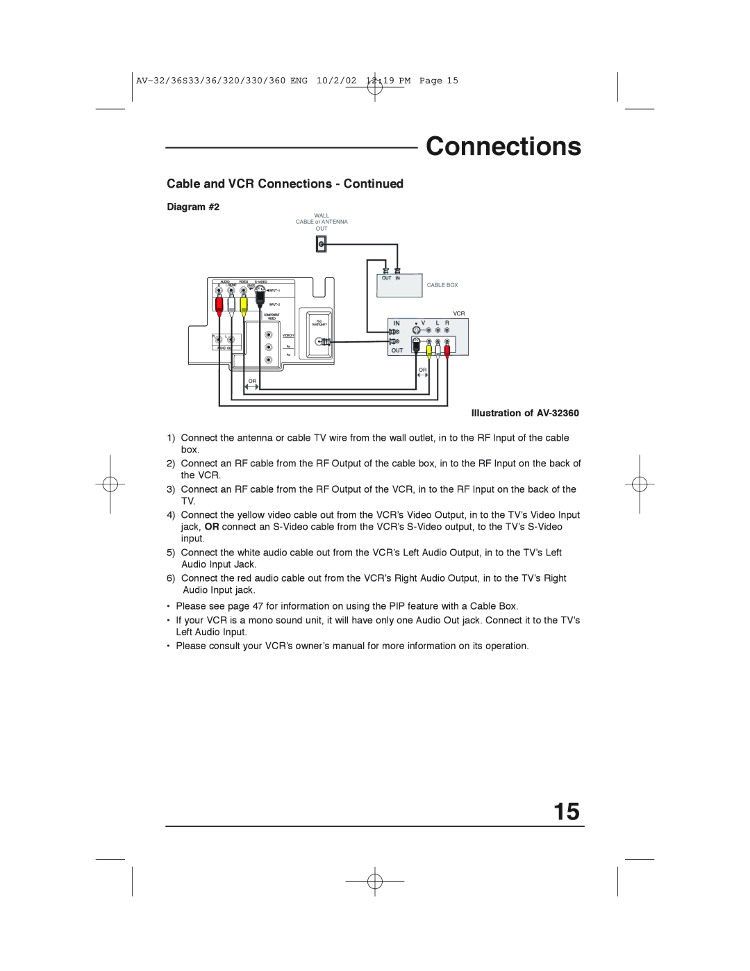
Diagram #2
WALL
CABLE or ANTENNA
OUT
CABLE BOX
VCR
OR
OR
Illustration of AV-32360
1)Connect the antenna or cable TV wire from the wall outlet, in to the RF Input of the cable box.
2)Connect an RF cable from the RF Output of the cable box, in to the RF Input on the back of the VCR.
3)Connect an RF cable from the RF Output of the VCR, in to the RF Input on the back of the TV.
4)Connect the yellow video cable out from the VCR’s Video Output, in to the TV’s Video Input jack, OR connect an
5)Connect the white audio cable out from the VCR’s Left Audio Output, in to the TV’s Left Audio Input Jack.
6)Connect the red audio cable out from the VCR’s Right Audio Output, in to the TV’s Right Audio Input jack.
•Please see page 47 for information on using the PIP feature with a Cable Box.
•If your VCR is a mono sound unit, it will have only one Audio Out jack. Connect it to the TV’s Left Audio Input.
•Please consult your VCR’s owner’s manual for more information on its operation.
15