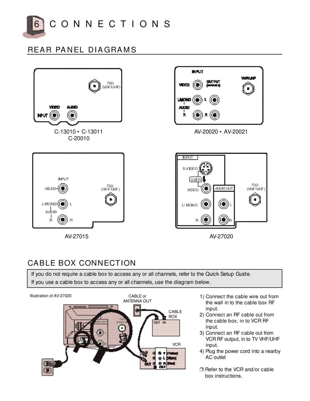
AV 27020, AV-27015, C-13010, AV-20021, C 13011 specifications
JVC has a longstanding reputation for producing quality audio and video equipment, and its series of consumer electronics, including the models C 13011, AV 27020, AV-20020, C-20010, and C-13010, are testament to the brand's commitment to innovation and performance.The JVC C 13011 is a compact stereo system that delivers impressive sound quality, making it a versatile choice for both casual listeners and audiophiles. One of its primary features is the built-in CD player, which supports various formats, including MP3 and WMA, allowing users to enjoy a wide range of music libraries. Additionally, the system incorporates an AM/FM tuner, providing access to local radio stations for diverse listening options. The C 13011 also features a digital display for easy navigation and control, while its sleek design ensures it fits seamlessly into any home décor.
Moving to the AV 27020, this model takes audio-visual performance to the next level. It comes equipped with advanced Dolby Digital technology, ensuring immersive sound for movies and music alike. The unit supports multiple inputs, making it easy to connect various devices, including DVD players, gaming consoles, and streaming devices. Its powerful surround sound system ensures that users experience an enveloping audio environment, enhancing overall viewing pleasure. A user-friendly interface simplifies navigation through settings and features, appealing to a wide range of users.
The AV-20020 model combines modern technology with user-friendly operation. This system features Bluetooth connectivity, allowing for seamless streaming from smartphones, tablets, and other Bluetooth-enabled devices. The built-in subwoofer enhances bass performance, making it ideal for those who enjoy powerful sound during movie nights or music playback. The AV-20020 also offers a range of customizable sound modes, enabling users to tailor audio output to their specific preferences.
The C-20010 and C-13010 models maintain JVC's tradition of delivering high-quality sound in compact units. The C-20010 is designed for simplicity, featuring a minimalistic interface that caters to users who prefer straightforward functionality. Meanwhile, the C-13010 is slightly more advanced, incorporating features like USB playback and equalizer settings to fine-tune audio output further.
Together, these JVC models showcase cutting-edge technology and thoughtful design, catering to various consumer needs while ensuring that high-quality audio and visual experiences are within reach. Each model stands out for its features, focusing on delivering clarity, power, and convenience, making JVC a trusted name in home entertainment systems.

