How to Install
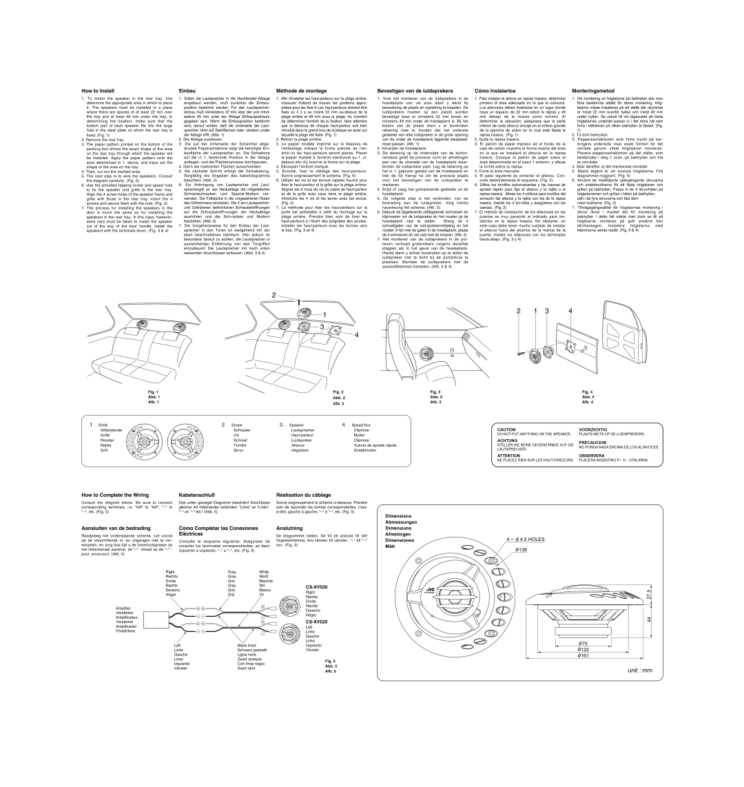
1.To install the speaker in the rear tray, first determine the appropriate area in which to place it. The speakers must be installed in a place where there are spaces of at least 22 mm over the tray and at least 49 mm under the tray. ln determining the location, make sure that the bottom part of each speaker fits into the large hole in the steel plate on which the rear tray is fixed. (Fig. 1)
2.Remove the rear tray.
3.The paper pattern printed on the bottom of the packing box shows the exact shape of the area on the rear tray through which the speaker will be installed. Apply the paper pattern onto the area determined in 1. above, and trace out the shape of the area on the tray.
4.Then, cut out the marked area.
5.The next step is to wire the speakers. Consult the diagram carefully. (Fig. 5)
6.Use the provided tapping screw and speed nuts to fix the speaker and grille to the rear tray. Align the 4 screw holes of the speaker frame and grille with those in the rear tray, insert the 4 screws and secure them with the nuts. (Fig. 2)
7.The process for installing the speakers in the door is much the same as for installing the speakers in the rear tray. ln this case, however, extra care must be taken to install the speaker out of the way of the door handle. lnstall the speakers with the terminals down. (Fig. 3 & 4)
Einbau
1.Sollen die Lautsprecher in die Heckfenster-Ablage eingebaut werden, muß zunächst die Einbau- position bestimmt werden. Für den Lautsprecher- einbau muß mindestens 22 mm über der und mind- estens 49 mm unter der Ablage Einbauspielraum gegeben sein. Wenn die Einbauposition bestimmt wird, darauf achten, daß die Unterseite der Laut- sprecher nicht auf Stahlflächen oder -streben under der Ablage trifft. (Abb. 1)
2.Die Ablage ausbauen.
3.Die auf der Unterseite der Schachtel abge- druckte Papierschablone zeigt die benötigte Ein- baufläche der Lautsprecher an. Die Schablone auf die in 1. bestimmte Position in der Ablage auflegen, und die Flächenumrisse durchpausen.
4.Dann die markierten Flächen ausschneiden.
5.Als nächster Schritt erfolgt die Verkabelung. Sorgfältig die Angaben des kabeldiagramms beachten! (Abb. 5)
6.Zur Anbringung von Lautsprecher und Laut- sprechergrill an der Heckablage die mitgelieferten Schneidschrauben und Spezial-Muttern ver- wenden. Die Füllstücke in die vorgesehenen Nuten des Grillrahmens einsetzen. Die 4 am Lautsprecher- und Grillrahmen befind-lichen Schraubenöffnungen auf die Schraubenöff-nungen der Heckablage ausrichten und die Sch-rauben und Muttern festziehen. (Abb. 2)
7.Die Vorgehensweise für den Einbau der Laut- sprecher in den Türen ist weitgehend mit der eben beschriebenen identisch. Hier jedoch ist besonders darauf zu achten, die Lautsprecher in ausreichender Entfernung von den Türgriffen einzubauen! Die Lautsprecher mit nach unten weisenden Anschlüssen einbauen. (Abb. 3 & 4)
Méthode de montage
1.Afin d'installer les haut-parleurs sur la plage arrière, s'assurer d'abord de trouver les positions appro- priées pour les fixer.k Les haut-parleurs doivent être fixés où il z a au moins 22 mm au-dessus de la plage arrière et 49 mm sous la plage. Au moment de déterminer l'endroit de la fixation, faire attention que le dessous de chaque haut-parleur soit bien introduit dans le grand trou de la plaque en acier sur laquelle la plage est fixée. (Fig. 1)
2.Retirer la plage arrière.
3.Le papier modèle imprimé sur le dessous de l'emballage indique la forme précise de l'en- droit où ies haut-parleurs seront placés. Placer le papier modèle à l'endroit mentionné au 1. ci- dessus afin d'y inscrire la forme sur la plage.
4.Découper l'endroit marqué.
5.Ensuite, fixer le câblage des haut-parleurs. Suivre soigneusement le schéma. (Fig. 5)
6.Utiliser les vis et les écrous rapides fournis pour fixer le haut-parleur et la grille sur la plage arrière. Aligner les 4 trous de vis du cadre de haut-parleur et de la grille avec ceux dans la plage arrière, introduire les 4 vis et les serrer avec les écous. (Fig. 2)
7.La méthode pour fixer les haut-parleurs sur la porte est semblable à celle du montage sur la plage arrière. Prendre bien soin de fixer les haut-parleurs à l'écart des poignées des poutes. lnstaller les haut-parleurs avec les bornes vers le bas. (Fig. 3 et 4)
Bevestigen van de luidsprekers
1.Voor het monteren van de luidsprekers in de hoedeplank van uw auto dient u eerst bij benadering de plaats en opstelling te bepalen. De luidsprekers moeten op een plaats worden bevestigd waar er minstens 22 mm boven en minstens 49 mm onder de hoedeplank is. Bij het kiezen van de plaats dient u er bovendien rekening mee te houden dat het onderste gedeelte van elke luidspreker in de grote opening van de onder de hoedeplank liggende staalplaat, moet passen. (Afb. 1)
2.Verwijder de hoedeplank.
3.De tekening op de onderzijde van de karton- nendoos geeft de precieze vorm en afmetingen aan van de uitsnede van de hoedeplank waar- binnen de luidspreker past. Leg de tekening op het in 1. gekozen gebied van de hoedeplank en trek de lijn hierop na om de precieze plaats voor het bevestigen van de luidspreker te markeren.
4.Snijd of zaag het gemarkeerde gedeelte uit de hoedeplank.
5.De volgede stap is het verbinden. van de bedrading aan de luidspreker. Volg hierbij nauwkeurig het schema. (Afb. 5)
6.Gebruik de bijgeleverde zelftappende schroeven en klipmoeren om de luidspreker en het rooster op de
hoedeplank vast te zetten. Breng de 4 schroefgaten van de luid-sprekeromlijsting en het rooster in lijn met de gaten in de hoedeplank, plaats de 4 schroeven dn zet vast met de moeren. (Afb. 2)
7.Het monteren van de luidsprekers in de por- tieren verloopt grotendeels volgens dezelfde stappen als in het geval van de hoedeplank. Hierbij dient u echter bovendien op te letten de luidspreker niet te dicht bij de portierkruk te plaatsen. Monteer de luidsprekers met de aansluitklemmen beneden. (Afb. 3 & 4)
Cómo lnstalarlos
1.Pala instalar el altaviz en repisa trasera, determine primero dl área adecuada en la que lo colocará. Los altavoces deben instalarse en un lugar donde haya un espacio de 22 mm sobre la repisa y 49 mm debajo de la misma como mínimo. Al determinar la ubicación, asegúrese que la parte inferior de cada altavoz encaje en el orificio grande de la plancha de acero en la cual está fijada la repisa trasera. (Fig. 1)
2.Quite la repisa trasera.
3.El patrón de papel impreso ed el fondo de la caja de cartón muestra la forma exacta del área en la que se instalará el altavoz en la repisa trasera. Coloque el patrón de papel sobre el área determinada en el paso 1 anterior, y dibuje la forma sobre la repisa.
4.Corte el área marcada.
5.El paso siguiente es conectar el altavoz. Con- sulte detenidamente el esquema. (Fig. 5)
6.Utilice los tornillos autorroscantes y las tuercas de apriete rápido para fijar el altavoz y la rejilla a la repisa trasera. Alinee los 4 orificios para tornillos del armazón del altavoz y la rejilla con los de la repisa trasera, inserte los 4 tor-nillos y asegúrelos con las tuercas. (Fig. 2)
7.El método de instalación de los altavoces en las puertas es muy parecido al indicado para ins- talarlos en la repisa trasera. No obstaner, en este caso debe tener mucho cuidado de instalar el altavoz fuera del alcance de la manija de la puerta. Instale los altavoces con los terminales hacia abajo. (Fig. 3 y 4)
Monteringsmetod
1.Vid montering av högtalarna på bakhyllan ska man först bestämma stället för deras montering. Hög- talarna måste installeras på ett ställe där utrymmet är minst 22 mm ovanför hyllan och minst 49 mm under hyllan. Se också till vid lägesvalet att båda högtalarnas underdel passar in i det stora hål som finns i stålskivan på vilken bakhyllan är fästad. (Fig. 1)
2.Ta bort bakhyllan.
3.Pappersschablonen som finns tryckt på kar- tongens undersida visar exakt formen för det område genom vilket högtalaren monteras. Placera pappersschablonen på det ställe, som bestämdes i steg 1 ovan, på bakhyllan och rita av området.
4.Skär därefter ut det markerade området.
5.Nästa åtgärd är att ansluta högtalarna. Följ diagrammet noggrant. (Fig. 5)
6.Använd de medföljante självgängande skruvarna och snabbmuttrarna för att fästa högtalaren och grillen på bakhyllan. Passa in de 4 skruvhålen på högtalarramen och grillen i hålen på bakhyllan, sätt i de fyra skruvarna och fäst dem
med muttrarna. (Fig. 2)
7.Tillvägagångssättet för högtalarnas montering i dörrar liknar i mycket det för montering på bakhyllan. l detta fall måste man dock se till att högtaiarna monteras på gott avstånd från dörrhantagen. lnstallera högtalarna med klämmorna vända nedåt. (Fig. 3 & 4)