7Using the MAKE/TRIGGER system

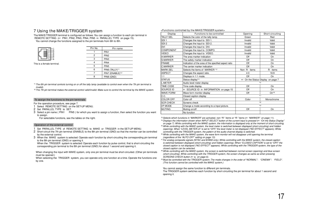
The MAKE/TRIGGER terminal is configured as follows. You can assign a function to each pin terminal in “REMOTE SETTING” (“PIN1, PIN2, PIN3, PIN4, PIN5” in “PARALLEL TYPE” on page 15).

• You cannot change the functions assigned to the pin terminals from 6th to 8th.


Pin No.

Pin name


1

PIN1


2

PIN2


3

PIN3


This is a female terminal.

4

PIN4

5

PIN5


6

PIN6 (TALLY)*1


7

PIN7 (ENABLE)*2


8

PIN8 (GND)

*1 The 6th pin terminal controls turning on or off the tally lamp (available to control even when the 7th pin terminal is invalid).

*2 The 7th pin terminal makes the external control valid/invalid. Make sure to control the terminal by the MAKE system.

To assign the functions to the pin terminals

For the operation procedure, see page 7.

1Select “REMOTE SETTING” on the SET-UP MENU.

2Set “PARALLEL TYPE” to “SET.”

3Select a pin name (“PIN1” – “PIN5”) for which you want to assign a function, then select the function you want to assign.

• For selectable functions, see the tables on the right.

Operation of the external control

1Set “PARALLEL TYPE” of “REMOTE SETTING” to “MAKE” or “TRIGGER” in the SET-UP MENU.

2Short-circuit the 7th pin terminal (ENABLE) to the 8th pin terminal (GND) so that the monitor can be controlled by the external control.

3When the “MAKE” system is selected: Operate each function by short-circuiting the corresponding pin terminal to the 8th pin terminal (GND) or opening it.

When the “TRIGGER” system is selected: Operate each function by pulse control, that is short-circuiting the corresponding pin terminal to the 8th pin terminal (GND) for about 1 second and opening it.

When changing the input with MAKE system, only one pin terminal must be short-circuited. (Other pin terminals must be opened.)

When selecting the “TRIGGER” system, you can operate only one function at a time. Operate the functions one by one.

<Functions controlled by the MAKE/TRIGGER system>

Display

Functions to be controlled

Opening


Short-circuiting

TALLY SEL

Selects the color of the tally lamp.

Green


Red

SDI 1

Changes the input to “SDI 1.”

Invalid


Valid

SDI 2

Changes the input to “SDI 2.”

Invalid


Valid

DVI

Changes the input to “DVI.”

Invalid


Valid

COMPONENT

Changes the input to “COMPO.”

Invalid


Valid

VIDEO

Changes the input to “VIDEO.”

Invalid


Valid

A.MARKER

The area marker indication

Off


On

S.MARKER

The safety marker indication

Off


On

FRAME

Indication of the area of the specified aspect ratio

Off


On

C.MARKER

The center marker indication

Off


On

MARK.SEL

Selects the items of “MARKER”*3

Non-“R-” items


“R-” items

ASPECT

Changes the aspect ratio.

4:3


16:9

1:1

Displays in 1:1 mode.

Off


On

STATUS

Status display*4

“On the Status Display” on page 7

L.METER

Audio level meter display


*5

TIME CODE

Time code display

Off


On

SOURCE ID

“SOURCE ID” in “INFORMATION” on page 15

Off


On

WAVE FORM

Wave form monitor display

Off


On*6

C.C.

Closed caption display


*7

COLOR OFF

Color off

Color


Monochrome

SCR CHECK

Screens check


*8

I/P MODE

Change a mode according to a input picture.


*9

MUTING

Muting on/off

Off


On

– – –

No function


*3 Selects which functions in “MARKER” are activated, non-“R-” items or “R-” items (“MARKER” on page 11).

*4 Displays the information shown when INPUT SELECT button of the current input is pressed (“On the Status Display” on page 7). While controlling with the MAKE system, the information is displayed only at the moment of short-circuiting.

*5 While controlling with the MAKE system, the level meter is switched between displayed (short-circuiting) and hidden (opening). When “LEVEL METER ch” is set to “OFF,” the level meter is not displayed (“NO EFFECT” appears). While controlling with the TRIGGER system, the pattern of the audio channel display is switched.

*6 While controlling with the MAKE system, the wave form monitor will not disappear until opening the terminal (regardless of the “AUTO OFF” setting on page 13).

*7 For analog composite signals (NTSC and B/W60 only). While controlling with the MAKE system, the closed caption is switched between displayed (short-circuiting) and hidden (opening). When “CLOSED CAPTION” is set to “OFF,” the closed caption is not displayed (“NO EFFECT” appears). While controlling with the TRIGGER system, the type of the closed caption can be selected.

*8 While controlling with the MAKE system, the screen is switched between normal screen (opening) and blue screen (short-circuiting). While controlling with the TRIGGER system, the screen changes as same as when pressing SCREENS CHECK button (q on page 6).

*9 Must be controlled with the TRIGGER system. The mode changes in the order of “NORMAL” \ “CINEMA” \ “FIELD”. (This function cannot be controlled with the MAKE system.)

You cannot assign the same function to different pin terminals.

The TRIGGER system switches each function by short-circuiting the pin terminal for about 1 second and opening it.

17

Page 17
Image 17
JVC DT-V17L3DY specifications Using the MAKE/TRIGGER system, To assign the functions to the pin terminals

DT-V17L3DY specifications

The JVC DT-V17L3DY is a compact, high-performance 17-inch LCD monitor designed for professional video applications. Tailored for broadcast and production environments, it delivers exceptional image quality and a range of features suited for demanding tasks.

One of the standout characteristics of the DT-V17L3DY is its high-resolution display, featuring a native resolution of 1920 x 1080 pixels, which is capable of displaying Full HD content with impressive clarity. The monitor boasts a wide viewing angle, ensuring that images remain consistent and vibrant from various positions. This is particularly advantageous in multi-user environments, such as control rooms or collaborative studios, where several individuals may be viewing the screen simultaneously.

The DT-V17L3DY utilizes advanced color reproduction technologies, resulting in rich and accurate colors. With a high contrast ratio, it provides deep blacks and bright whites, enhancing the overall viewing experience. To further refine color accuracy, it supports a built-in color calibration feature, allowing users to adjust settings according to specific requirements or standards, making it an excellent choice for color-critical work such as film and video production.

In terms of connectivity, the monitor is equipped with a variety of input options, including HDMI, SDI, and analog connections. This versatility ensures compatibility with a wide range of video sources, accommodating different workflows and setups. Furthermore, the DT-V17L3DY supports both interlaced and progressive signal formats, making it adaptable to a broad spectrum of broadcasting standards.

The monitor's ergonomic design features a sturdy and lightweight chassis, making it suitable for both desktop and rack-mounted applications. Its flexible mounting options allow for easy integration into any setup, whether in a studio, on location, or within an OB van.

Additional features include embedded audio monitoring capabilities, allowing users to check audio levels directly from the monitor, and a set of user-friendly controls for adjusting settings quickly and intuitively. This combination of advanced technology, exceptional display quality, and practical usability makes the JVC DT-V17L3DY a reliable choice for professionals in the video production industry. Whether used for editing, monitoring, or playback, this monitor stands out as a valuable tool for achieving the highest standards in broadcast quality.