External Control (cont.)

7Using the serial communication

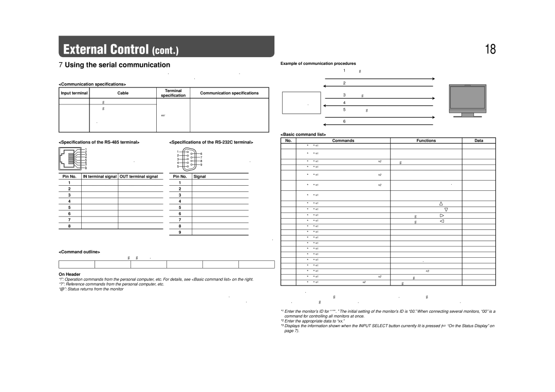
You can control the monitor from a personal computer etc. via the RS-485 or RS-232C terminal.

• Consult your dealer for the details of the external control specification.

<Communication specifications>


Input terminal


Cable


Terminal


Communication specifications


specification


RS-485


A straight LAN cable


Baud Rate: 4800 bps


RS-232C


A straight cable with a D-sub 9-pin


Data Bits: 8 bits


connector (male for the monitor,


See below

Parity: No parity


female for the personal computer


Stop Bits: 1 bit


etc.)


Flow Control: No control


Communication Code: ASCII Code


<Specifications of the RS-485 terminal>


<Specifications of the RS-232C terminal>


This is a female terminal.


This is a female terminal.


Pin No.

IN terminal signal

OUT terminal signal


Pin No.


Signal


1


TXD +

TXD +


1


NC


2


TXD –

TXD –


2


RXD


3


RXD +

RXD +


3


TXD


4


NC

NC


4


NC


5


NC

NC


5


GND


6


RXD –

RXD –


6


NC


7


NC

NC


7


RTS


8


GND

GND


8


CTS


9


NC


• The 7th terminal and the 8th terminal are connected.

<Command outline>

All commands consist of the following segments.

Header

Monitor ID

Command ID

Function

Data

Cr (0DH)


On Header

“!”: Operation commands from the personal computer, etc. For details, see <Basic command list> on the right.

“?”: Reference commands from the personal computer, etc.

“@”: Status returns from the monitor

To start communication, send the connection command from the personal computer etc.

To terminate the communication, send the termination command from the personal computer etc.

18

Example of communication procedures


1Starting the communication:


connection command (!00BCN1Cr)


Monitor


2Monitor’s status (@00BOKCr)


3Selecting “SDI 1” input (!00BINACr)


PC, etc.


4Monitor’s status (@00BOKCr)


5Terminating the communication: termination command


(!00BCN0Cr)


6Monitor’s status (@00BOKCr)


<Basic command list>


No.


Commands


Functions


Data

1


!

*

**1

B

C

N

1

Cr


Starts communication (connection)

No data

2


!

*

**1

B

C

N

0

Cr


Terminates communication


No data


(termination)


3


!

*

**1

B

I

D

S

E

T

x

x*2

Cr

Assigns the control ID


01 – 99

4


!

*

**1

B

I

D

R

E

T

Cr


Initializes the control ID


No data

5


!

*

**1

B

I

D

D

S

P

x

x*2

Cr

Displays/hides the ID


00: Hide


01: Display


6


!

*

**1

B

I

D

C

H

K

x

x*2

Cr

Flashes/hides the selected ID No. of

00: Hide


the monitor


01: Display

7


!

*

**1

B

M E

N

U

Cr


Displays the MAIN MENU/Quits the

No data


menu operation


8


!

*

**1

B

U

P

Cr


Moves the cursor upward (

)


No data

9


!

*

**1

B

D

O

W

N

Cr


Moves the cursor downward ( )

No data

10


!

*

**1

B

A

D

J

R

Cr


Makes setting/adjustment (

)


No data

11


!

*

**1

B

A

D

J

L

Cr


Makes setting/adjustment (

)


No data

12


!

*

**1

B

S

E

T

U

P

Cr


Displays the SET-UP MENU


No data

13


!

*

**1

B

P

W

1

Cr


Turns on the monitor


No data

14


!

*

**1

B

P

W

0

Cr


Turns off the monitor (on standby)

No data

15


!

*

**1

B

I

N

A

Cr


Selects “SDI 1” input


No data

16


!

*

**1

B

I

N

B

Cr


Selects “SDI 2” input


No data

17


!

*

**1

B

I

N

C

Cr


Selects “DVI” input


No data

18


!

*

**1

B

I

N

D

Cr


Selects “COMPO.” input


No data

19


!

*

**1

B

I

N

E

Cr


Selects “VIDEO” input


No data

20


!

*

**1

B

D

I

S

P

Cr


Displays the status*3


No data

21


!

*

**1

B

A

M

U

T

E

x

x*2

Cr

Turns muting on/off


00: Off, 01: On

22


!

*

**1

B

A

S

P

x

x*2

Cr


Changes the aspect ratio


00: 4:3, 01: 16:9

“Cr” is 0Dh.

The commands for starting communication (connection) (No. 1), terminating communication (termination) (No. 2), and turning on the monitor (No. 13) can be used while the monitor is off (on standby).

*1 Enter the monitor’s ID for “ **.” The initial setting of the monitor’s ID is “00.” When connecting several monitors, “00” is a command for controlling all monitors at once.

*2 Enter the appropriate data to “xx.”

*3 Displays the information shown when the INPUT SELECT button currently lit is pressed (“On the Status Display” on page 7).

Page 18
Image 18
JVC DT-V17L3DY Using the serial communication, Communication specifications, Command outline, On Header

DT-V17L3DY specifications

The JVC DT-V17L3DY is a compact, high-performance 17-inch LCD monitor designed for professional video applications. Tailored for broadcast and production environments, it delivers exceptional image quality and a range of features suited for demanding tasks.

One of the standout characteristics of the DT-V17L3DY is its high-resolution display, featuring a native resolution of 1920 x 1080 pixels, which is capable of displaying Full HD content with impressive clarity. The monitor boasts a wide viewing angle, ensuring that images remain consistent and vibrant from various positions. This is particularly advantageous in multi-user environments, such as control rooms or collaborative studios, where several individuals may be viewing the screen simultaneously.

The DT-V17L3DY utilizes advanced color reproduction technologies, resulting in rich and accurate colors. With a high contrast ratio, it provides deep blacks and bright whites, enhancing the overall viewing experience. To further refine color accuracy, it supports a built-in color calibration feature, allowing users to adjust settings according to specific requirements or standards, making it an excellent choice for color-critical work such as film and video production.

In terms of connectivity, the monitor is equipped with a variety of input options, including HDMI, SDI, and analog connections. This versatility ensures compatibility with a wide range of video sources, accommodating different workflows and setups. Furthermore, the DT-V17L3DY supports both interlaced and progressive signal formats, making it adaptable to a broad spectrum of broadcasting standards.

The monitor's ergonomic design features a sturdy and lightweight chassis, making it suitable for both desktop and rack-mounted applications. Its flexible mounting options allow for easy integration into any setup, whether in a studio, on location, or within an OB van.

Additional features include embedded audio monitoring capabilities, allowing users to check audio levels directly from the monitor, and a set of user-friendly controls for adjusting settings quickly and intuitively. This combination of advanced technology, exceptional display quality, and practical usability makes the JVC DT-V17L3DY a reliable choice for professionals in the video production industry. Whether used for editing, monitoring, or playback, this monitor stands out as a valuable tool for achieving the highest standards in broadcast quality.