52 EN | CONNECTIONS Basic Connections |
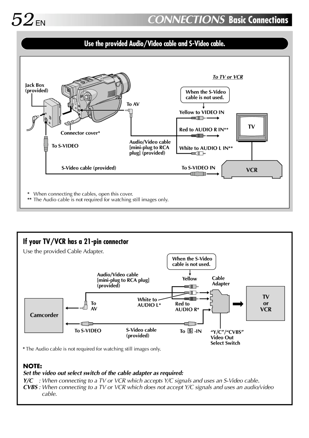
Use the provided Audio/Video cable and S-Video cable.
Jack Box (provided)
To TV or VCR
When the
Connector cover*
To AV
Audio/Video cable
p
Yellow to VIDEO IN
Red to AUDIO R IN**
TV |
To
White to AUDIO L IN**
To | VCR | ||||||
|
|
|
|
|
|
|
|
|
|
|
|
|
|
|
|
*When connecting the cables, open this cover.
**The Audio cable is not required for watching still images only.
If your TV/VCR has a 21-pin connector
Use the provided Cable Adapter.
|
| When the | |
|
| cable is not used. |
|
Audio/Video cable | p | Cable | |
Yellow | |||
(provided) |
|
| Adapter |
|
|
| |
To | White to | Red to |
|
AUDIO L* |
| ||
AV |
| AUDIO R* |
|
Camcorder |
|
|
|
To | To | “Y/C”/“CVBS” | |
| (provided) |
| Video Out |
|
|
| |
Select Switch
*The Audio cable is not required for watching still images only.
NOTE:
Set the video out select switch of the cable adapter as required:
TV or
VCR
Y/C : When connecting to a TV or VCR which accepts Y/C signals and uses an
CVBS : When connecting to a TV or VCR which does not accept Y/C signals and uses an audio/video cable.