74![]()
![]()
![]() EN
EN![]()
![]()
![]()
![]()
![]()
![]()
![]()
![]()
![]()
CONTROLS,
 INDICATIONS
 AND
AND
 CONNECTORS


Camcorder
| 1 |
| 2 |
| 3 |
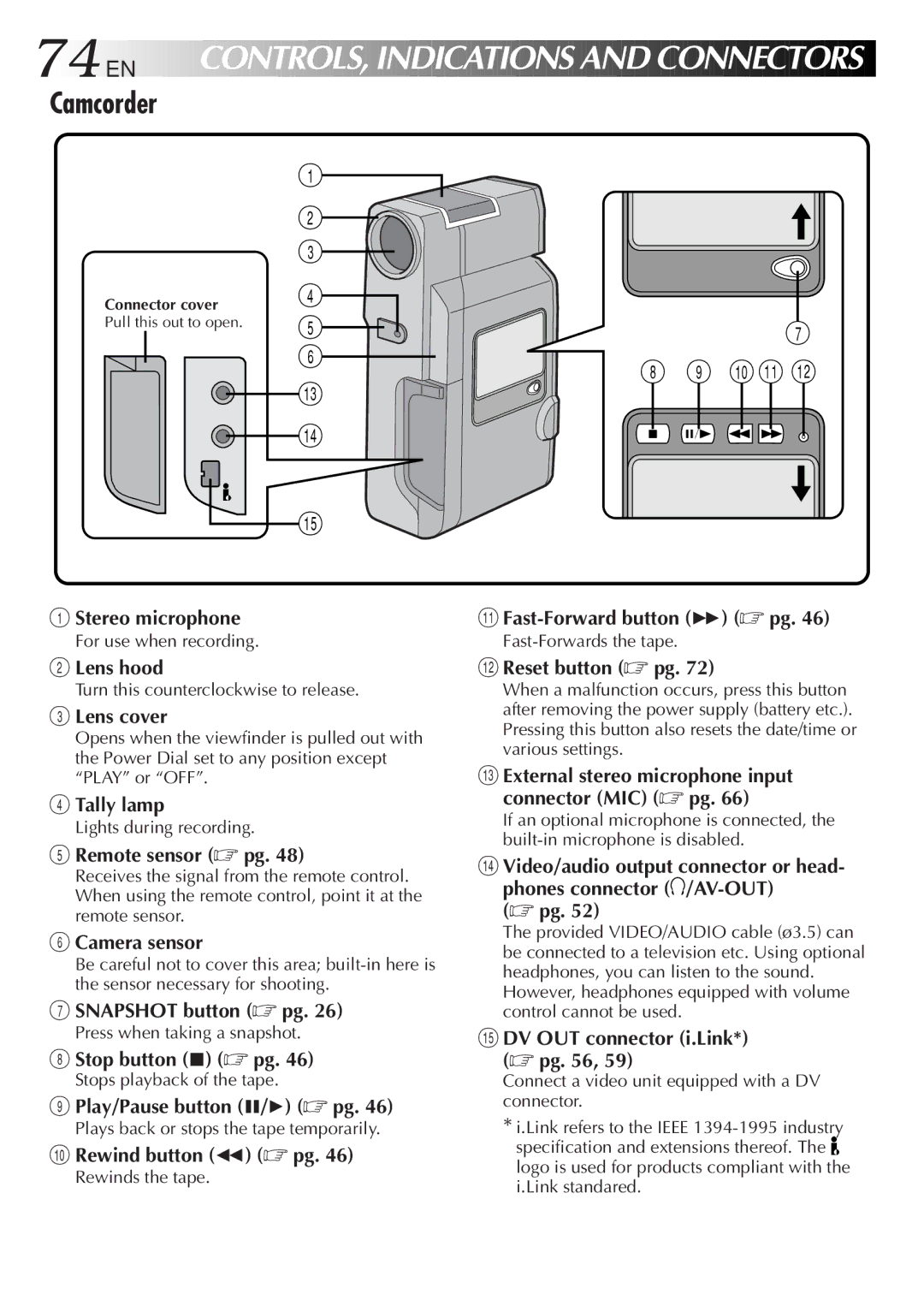
Connector cover | 4 |
Pull this out to open. | 5 |
| |
| 6 |
| # |
| $ |
| % |
7
8 9 0! @
1Stereo microphone
For use when recording.
2Lens hood
Turn this counterclockwise to release.
3Lens cover
Opens when the viewfinder is pulled out with the Power Dial set to any position except “PLAY” or “OFF”.
4Tally lamp
Lights during recording.
5Remote sensor (☞ pg. 48)
Receives the signal from the remote control. When using the remote control, point it at the remote sensor.
6Camera sensor
Be careful not to cover this area;
7SNAPSHOT button (☞ pg. 26)
Press when taking a snapshot.
8Stop button (5) (☞ pg. 46)
Stops playback of the tape.
9Play/Pause button (6/4) (☞ pg. 46)
Plays back or stops the tape temporarily.
0Rewind button (2) (☞ pg. 46)
Rewinds the tape.
!
@Reset button (☞ pg. 72)
When a malfunction occurs, press this button after removing the power supply (battery etc.). Pressing this button also resets the date/time or various settings.
#External stereo microphone input connector (MIC) (☞ pg. 66)
If an optional microphone is connected, the
$Video/audio output connector or head- phones connector ![]() /AV-OUT)
/AV-OUT)
(☞ pg. 52)
The provided VIDEO/AUDIO cable (ø3.5) can be connected to a television etc. Using optional headphones, you can listen to the sound. However, headphones equipped with volume control cannot be used.
%DV OUT connector (i.Link*) (☞ pg. 56, 59)
Connect a video unit equipped with a DV connector.
*i.Link refers to the IEEE
specification and extensions thereof. The ![]() logo is used for products compliant with the i.Link standared.
logo is used for products compliant with the i.Link standared.