– Buttons, Connectors and Indicators –
Remote
POWER
Number keys
AUX
REC
REW
STOP
MENU
TV/VCR
A.MONITOR
TV POWER
INPUT
TV
POWER
1 2 3
4 | 5 |
| 6 | ||
7 | 8 |
| 9 |
|
|
0(AUX) |
| – | CH | + | PAUSE |
|
|
|
|
| |
REC | PLAY | PAUSE |
| ||
|
|
| |||
|
|
|
|
| PLAY |
REW |
|
|
| FF | FF |
|
|
|
|
| ENTER |
MENU |
|
| ENTER | TIMER | |
| STOP |
| |||
| – | SET | + |
| |
|
|
|
|
| CANCEL |
TV/VCR |
| TIMER | C.RESET | C.RESET | |
|
|
| CANCEL |
| |
A.MONITOR |
| SP/EP | DISPLAY | SP/EP | |
TV POWER |
| – | TV CH | + | DISPLAY |
INPUT |
| – | TV VOL | + |
|
TV
Connections and VCR channel Setting
1Check contents
Make sure the package contains all of the accessories listed in “Specifications”.
2Situate VCR
Place the VCR on a stable, horizontal surface.
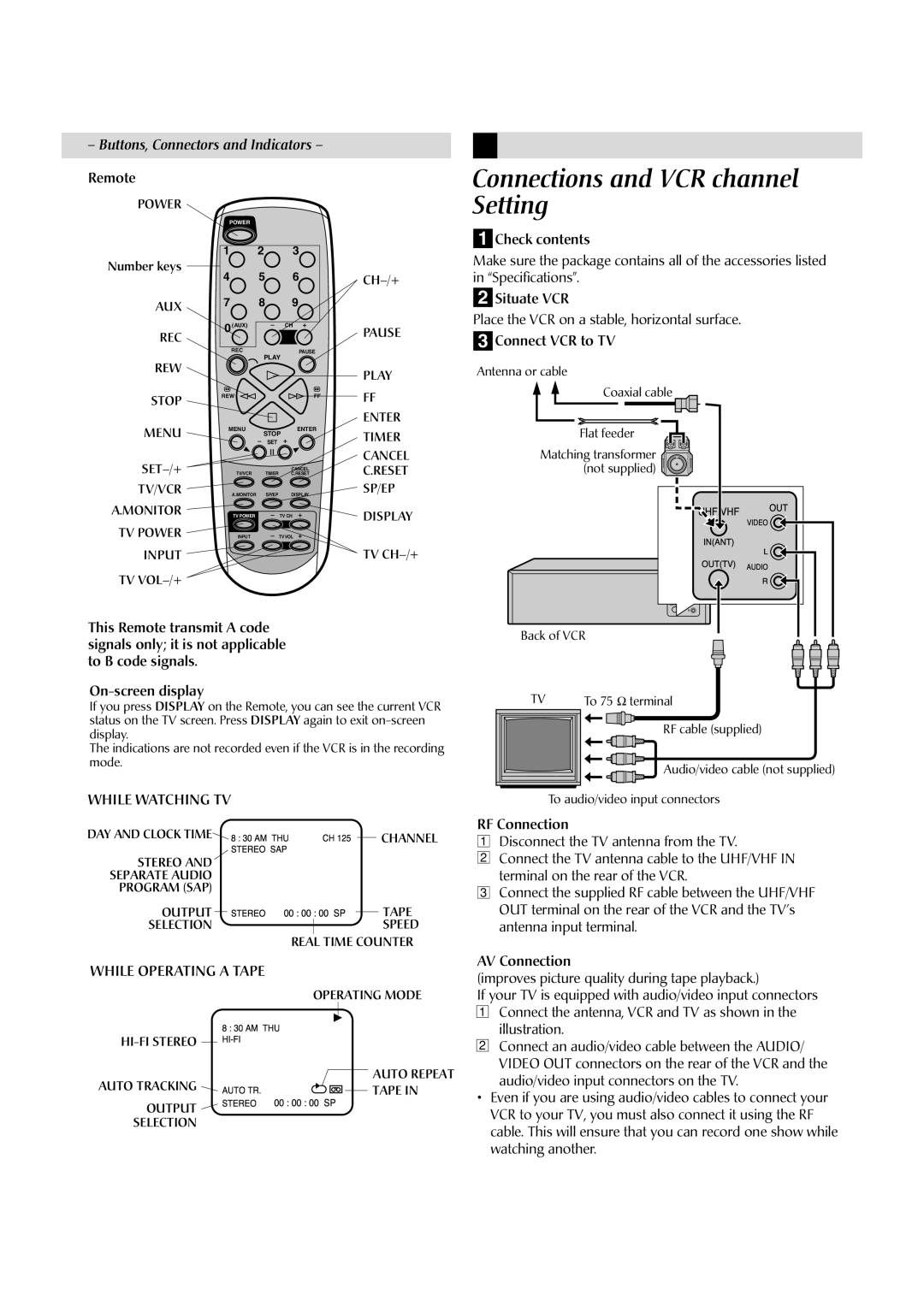
3Connect VCR to TV
Antenna or cable
Coaxial cable |
|
|
|
Flat feeder | IN(ANT) | VIDEO |
|
Matching transformer |
| ||
UHF/VHF |
| OUT | |
(not supplied) | AUDIORL | ||
| OUT(TV) |
|
This Remote transmit A code signals only; it is not applicable to B code signals.
If you press DISPLAY on the Remote, you can see the current VCR status on the TV screen. Press DISPLAY again to exit
The indications are not recorded even if the VCR is in the recording mode.
WHILE WATCHING TV
DAY AND CLOCK TIME |
|
| 8STEREOSTEREO:30AMSAPTHU00:00:00CHSP125 |
|
| CHANNEL | ||||||||
STEREO AND |
|
|
|
|
|
|
|
|
|
|
|
|
| |
SEPARATE AUDIO |
|
|
|
|
|
|
|
|
|
|
|
|
| |
PROGRAM (SAP) |
|
|
|
|
|
|
|
|
|
|
|
|
| |
OUTPUT |
|
|
|
|
|
|
|
|
|
|
|
| TAPE | |
|
|
|
|
|
|
|
|
|
|
|
| |||
SELECTION |
|
|
|
|
|
|
|
|
|
|
|
| SPEED | |
WHILE OPERATING A TAPE | REAL | TIME COUNTER | ||||||||||||
|
|
|
|
|
|
|
|
| ||||||
|
|
| THU | OPERATING MODE | ||||||||||
|
|
| STEREO | 00:00:00SP |
|
|
|
| TAPE IN | |||||
|
|
|
| |||||||||||
|
| AUTOTR. |
|
|
|
|
|
|
|
| AUTO REPEAT | |||
|
|
|
|
|
|
|
|
|
| |||||
AUTO TRACKING |
|
|
|
|
|
|
|
|
| |||||
|
|
|
|
|
|
|
|
| ||||||
|
|
|
|
|
|
|
|
|
| |||||
OUTPUT
SELECTION
Back of VCR
TV | To 75 Ω terminal |
| RF cable (supplied) |
| Audio/video cable (not supplied) |
| To audio/video input connectors |
RF Connection
1Disconnect the TV antenna from the TV.
2Connect the TV antenna cable to the UHF/VHF IN terminal on the rear of the VCR.
3Connect the supplied RF cable between the UHF/VHF OUT terminal on the rear of the VCR and the TV’s antenna input terminal.
AV Connection
(improves picture quality during tape playback.)
If your TV is equipped with audio/video input connectors
1Connect the antenna, VCR and TV as shown in the illustration.
2Connect an audio/video cable between the AUDIO/ VIDEO OUT connectors on the rear of the VCR and the audio/video input connectors on the TV.
•Even if you are using audio/video cables to connect your VCR to your TV, you must also connect it using the RF cable. This will ensure that you can record one show while watching another.
