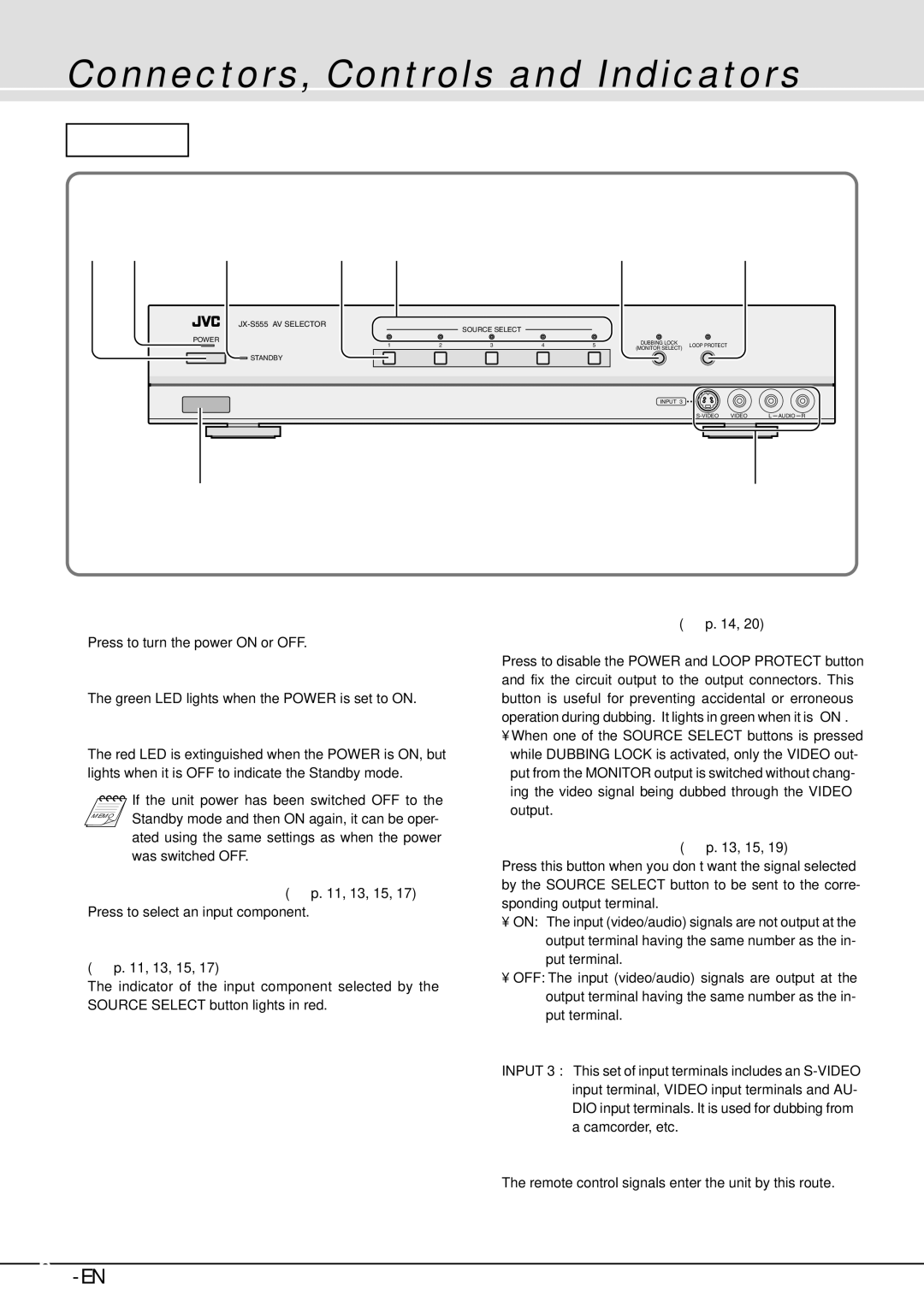
JX-B555 specifications
The JVC JX-B555 is an innovative and versatile audio device that has gained recognition for its uncompromising sound quality and cutting-edge technology. Designed for audiophiles and casual listeners alike, the JX-B555 promises to elevate the listening experience across various genres and formats.One of the standout features of the JVC JX-B555 is its advanced digital signal processing (DSP) technology. This allows for precise sound shaping, ensuring that audio is reproduced with exceptional clarity and detail. Whether you’re listening to your favorite music or watching movies, the sound quality from the JX-B555 remains consistently impressive.
The JX-B555 also boasts a comprehensive range of connectivity options. With Bluetooth capabilities, users can effortlessly stream music from their smartphones, tablets, or laptops, making it an excellent choice for modern-day listeners who prioritize convenience. Additionally, the device supports various audio formats, including lossless formats, ensuring that no detail in your favorite tracks is lost during playback.
In terms of design, the JVC JX-B555 is sleek and modern, featuring a user-friendly interface that includes an intuitive remote control. The device is equipped with high-quality speakers that deliver powerful bass and clear highs, making it suitable for parties or quieter, more intimate settings. The adjustable equalizer allows users to customize their sound profile according to personal preference, enhancing the listening experience even further.
Another noteworthy characteristic of the JX-B555 is its durability. Built with high-grade materials, this audio device is designed to withstand the rigors of daily use while providing long-lasting performance. The JX-B555 also incorporates energy-efficient technology, ensuring that it operates with minimal power consumption without sacrificing sound quality.
For those who appreciate visual aesthetics, the JVC JX-B555 is available in multiple color options, allowing users to select a style that complements their personal taste and interior decor. Overall, the JVC JX-B555 combines functionality, advanced technologies, and aesthetic appeal to create a well-rounded audio device that meets the demands of today’s music lovers. With its exceptional sound quality, versatile connectivity, and durable design, the JVC JX-B555 is an investment worth considering for anyone serious about audio enjoyment.

