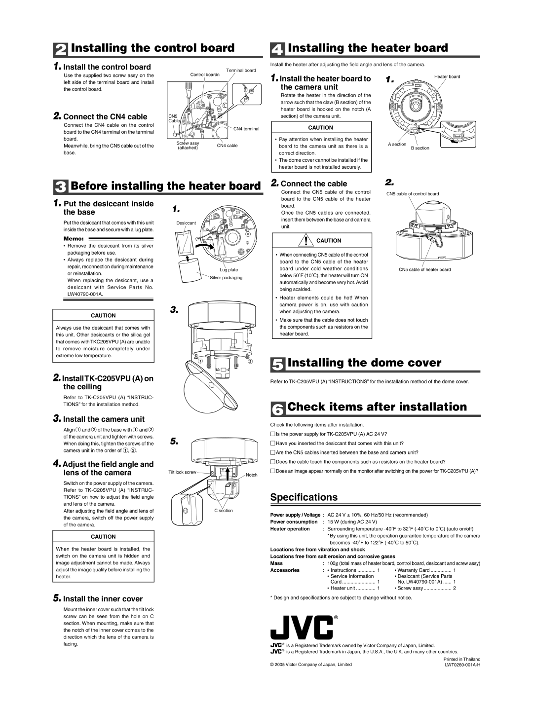
2 Installing the control board

1. Install the control board

Terminal board

4 Installing the heater board

Install the heater after adjusting the field angle and lens of the camera.

Use the supplied two screw assy on the left side of the terminal board and install the control board.

2. Connect the CN4 cable

Connect the CN4 cable on the control board to the CN4 terminal on the terminal board.

Meanwhile, bring the CN5 cable out of the base.

Control boardn

1. Install the heater board to


the camera unit


Rotate the heater in the direction of the


arrow such that the claw (B section) of the


heater board is hooked on the notch (A

CN5


section) of the camera unit.

Cable


CN4 terminal


CAUTION

Screw assy


Pay attention when installing the heater

CN4 cable


board to the camera unit as there is a

(attached)


correct direction.


The dome cover cannot be installed if the


heater board is not installed securely.

1.

Heater board


A section

B section

3 Before installing the heater board

2. Connect the cable

Connect the CN5 cable of the control

2.

CN5 cable of control board

1. Put the desiccant inside the base

Put the desiccant that comes with this unit inside the base and secure with a lug plate.

Memo:

Remove the desiccant from its silver packaging before use.

Always replace the desiccant during repair, reconnection during maintenance or reinstallation.

When replacing the desiccant, use a desiccant with Service Parts No. LW40790-001A.

1.

Desiccant

Lug plate

Silver packaging

board to the CN5 cable of the heater board.

Once the CN5 cables are connected, insert them between the base and camera unit.

CAUTION

When connecting CN5 cable of the control

board to the CN5 cable of the heater

board under cold weather conditions

below 50˚F (10˚C), the heater will turn ON

automatically and become very hot. Avoid

being scalded.

Heater elements could be hot! When

camera power is on, use with caution

CN5 cable of heater board

3.

CAUTION

Always use the desiccant that comes with this unit. Other desiccants or the silica gel that comes with TKC205VPU (A) are unable to remove moisture completely under extreme low temperature.

1 2

when adjusting the camera.

Make sure that the cable does not touch

the components such as resistors on the

heater board.

5 Installing the dome cover

2. InstallTK-C205VPU (A) on the ceiling

Refer to TK-C205VPU (A) “INSTRUC- TIONS” for the installation method.

3. Install the camera unit

Align 1 and 2 of the base with 1 and 2 of the camera unit and tighten with screws. When doing this, tighten the screws of the camera unit in the order of 1, 2.

4. Adjust the field angle and lens of the camera

Switch on the power supply of the camera. Refer to TK-C205VPU (A) “INSTRUC- TIONS” on how to adjust the field angle and lens of the camera.

After adjusting the field angle and lens of the camera, switch off the power supply of the camera.

CAUTION

When the heater board is installed, the switch on the camera unit is hidden and image adjustment cannot be made. Always adjust the image quality before installing the heater.

5. Install the inner cover

Mount the inner cover such that the tilt lock screw can be seen from the hole on C section. When mounting, make sure that the notch of the inner cover comes to the direction which the lens of the camera is facing.

5.

Tilt lock screw

Notch

C section

Refer to TK-C205VPU (A) “INSTRUCTIONS” for the installation method of the dome cover.

6 Check items after installation

Check the following items after installation.

Is the power supply for TK-C205VPU (A) AC 24 V?

Have you inserted the desiccant that comes with this unit?

Are the CN5 cables inserted between the base and camera unit?

Does the cable touch the components such as resistors on the heater board?

Does an image appear normally on the monitor after switching on the power for TK-C205VPU (A)?

Specifications

Power supply / Voltage :

AC 24 V ± 10%, 60 Hz/50 Hz (recommended)


Power consumption

:

15 W (during AC 24 V)


Heater operation

: Surrounding temperature -40˚F to 32˚F (-40˚C to 0˚C) (auto on/off)


*By using this unit, the operation guarantee temperature of the camera


becomes -40˚F to 122˚F (-40˚C to 50˚C).


Locations free from vibration and shock


Locations free from salt erosion and corrosive gases


Mass

:

100˝ (total mass of heater board, control board, desiccant and screw assy)

Accessories

: Instructions

1

Warranty Card

1


Service Information


Desiccant (Service Parts


Card

1

No. LW40790-001A)

1


Heater unit

1

Screw assy

2

*Design and specifications are subject to change without notice.

®

® is a Registered Trademark owned by Victor Company of Japan, Limited.

® is a Registered Trademark in Japan, the U.S.A., the U.K. and many other countries.


Printed in Thailand

© 2005 Victor Company of Japan, Limited

LWT0260-001A-H

Page 2
Image 2
JVC KA-H205U user service Installing the control board, Installing the heater board, Before installing the heater board

KA-H205U specifications

The JVC KA-H205U is a versatile and professional-grade editing and production switcher, aimed primarily at live event production, videography, and broadcasting environments. Known for its robust features and ease of use, it has gained a reputation among professionals for its reliability and performance.

One of its core features is the ability to switch between multiple video sources seamlessly. The KA-H205U supports up to 4 HD-SDI inputs, allowing users to connect various cameras and video devices, making it suitable for multi-camera setups. The HD-SDI inputs support resolutions up to 1080p, ensuring high-quality video output. The low latency switching makes it optimal for live events where timing is critical.

The switcher also boasts a built-in digital video effects generator. Users can apply a variety of transitions, such as wipes and fades, adding a professional polish to their productions. Additionally, the KA-H205U allows for preview and program outputs, which is essential for monitoring purposes. This feature helps operators ensure that transitions and effects are fluid and visually appealing before they go live.

Another significant aspect of the JVC KA-H205U is its audio capabilities. It includes support for embedded audio over HD-SDI, as well as separate audio inputs, allowing for synchronized sound to accompany video. This is particularly useful in live event scenarios where audio quality is crucial for audience engagement.

The interface of the KA-H205U is user-friendly, featuring an intuitive layout with clear labeling for each function. This design minimizes the learning curve for new users while providing experienced operators with efficient control over their productions. Additionally, the compact design makes it easy to transport, catering to mobile production teams.

In terms of connectivity, the JVC KA-H205U offers various options, including USB, allowing for external storage or live streaming capabilities. Compatibility with industry-standard protocols ensures it can integrate easily into existing production setups.

The durability and construction of the KA-H205U appeal to professionals working in demanding environments. Its design is built to withstand frequent movement and use, making it a reliable choice for on-the-go production crews.

In summary, the JVC KA-H205U combines advanced video switching capabilities with professional audio handling and a user-friendly interface, making it a standout choice for video professionals seeking a reliable and effective solution for live production needs.