BNC connector box
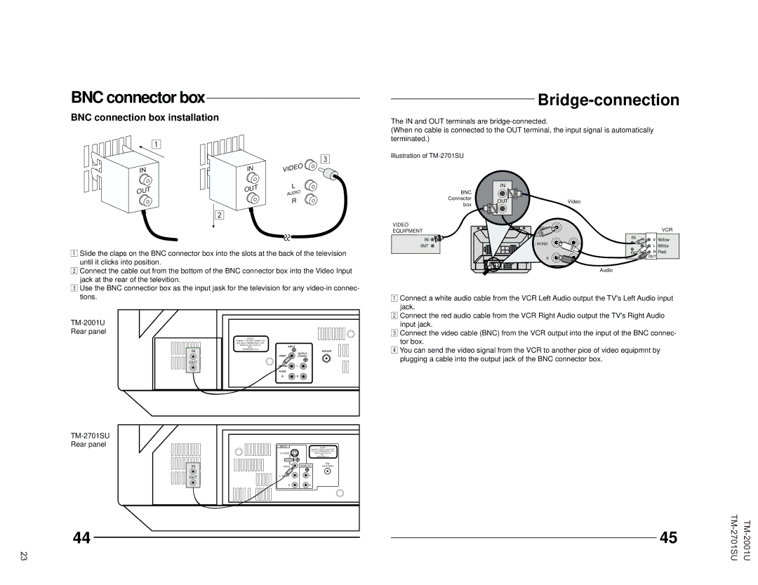
BNC connection box installation
1
IN
3
IN | VIDEO |
Bridge-connection
The IN and OUT terminals are
(When no cable is connected to the OUT terminal, the input signal is automatically terminated.)
Illustration of
OUT
2
OUT | L | |
AUDIO | ||
| ||
| R |
BNC Connector box
VIDEO
EQUIPMENT
IN ![]()
![]()
![]()
IN
OUT
| Video |
| |
|
| VCR | |
| IN | Yellow | |
L/ MONO | L | ||
White | |||
|
|
1Slide the claps on the BNC connector box into the slots at the back of the television until it clicks into position.
2Connect the cable out from the bottom of the BNC connector box into the Video Input jack at the rear of the televition.
3Use the BNC connectior box as the input jask for the television for any
Rear panel
NOTICE
CONNECT THE BNC CONNECTOR
BOX (AUTO TERMINATION). THIS
| Red |
R | IN |
|
Audio
1Connect a white audio cable from the VCR Left Audio output the TV's Left Audio input
jack.
2Connect the red audio cable from the VCR Right Audio output the TV's Right Audio input jack.
3Connect the video cable (BNC) from the VCR output into the input of the BNC connec-
tor box.
IN
NOT
TERMINATED 75 Ω
4 You can send the video signal from the VCR to another pice of video equipmnt by |
plugging a cable into the output jack of the BNC connector box. |
OUT
TM-2701SU
Rear panel
IN
OUT
44
23
INPUT |
| NOTICE |
| CONNECT THE BNC CONNECTOR | |
| BOX (AUTO TERMINATION). THIS | |
| ||
|
| NOT |
|
| TERMINATED 75 Ω |
OVER |
|
|
| AUDIO OUT | 75Ω |
VIDEO | (VHF/UHF) | |
L/ MONO | L |
|
R | R |
|
45 | ||
|
|