4): Indicates the

1-6

HOW TO USE THE MENU FUNCTIONS (cont’d)

DISPLAY AND SELECTIONS IN THE <SET-UP MENU> MODE (SETTING)


Set-up menu items


Purpose


Settings


PICTURE SUB ADJ.

Image sub adjustment


Selects CONTRAST/BRIGHT/CHROMA/PHASE. The


selected setting screen is shown. Select the function display for


adjustment.


CONTRAST

Adjusts contrast.


–10


–9 • • –01

00


+01

• • +09

+10


BRIGHT


Adjusts brightness.


–10


–9 • • –01

00


+


• •

+


+


01

09

10


CHROMA

Adjusts color density.

*1


–10


–9 • • –01

00


+


• •

+


+


01

09

10


PHASE


Adjusts hue.

*1


–10


–9 • • –01

00


+


• •

+


+


01

09

10


H. POSITION


Adjusts the horizontal position of the


screen (+: Horizontal position shifts


–5

• • • –01

00

+1


• • • +5

TM-H1900G

You can set the following set-up menu items.

• PICTURE SUB ADJ.

• WHITE BALANCE

• REMOTE SYSTEM

• H. POSITION

• CONTROL LOCK

• INPUT REMOTE

• V. POSITION

• STATUS DISPLAY


Notes:

Parameters for PICTURE SUB ADJ., H. POSITION and V. POSITION can be set separately depending on the signal (Input A (VIDEO), Input B (VIDEO) or Input B (Y/ C)) selected with the input select buttons on the front panel.

Select the required video input with the input select buttons on the front panel in advance.

WHITE BALANCE can be set independently at 6500 or 9300 for the color temperature value.

Set COLOR TEMP. to 6500 or 9300 on the <MENU> screen beforehand.

INPUT REMOTE is shown when REMOTE SYSTEM is set to MAKE.

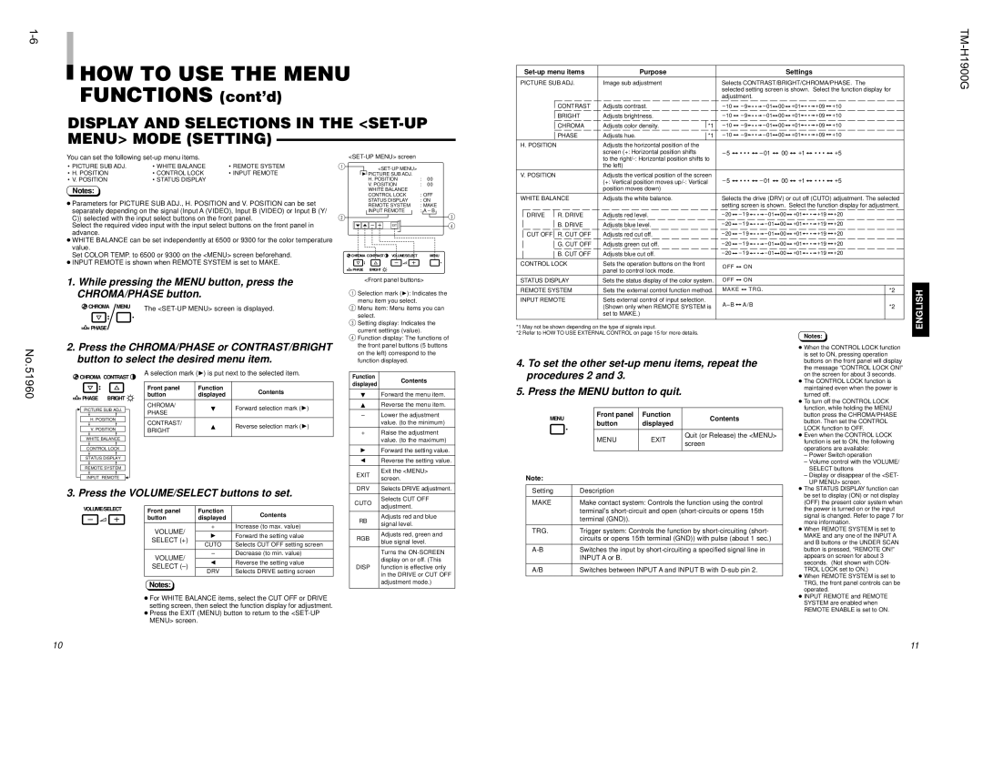
1.While pressing the MENU button, press the CHROMA/PHASE button.

CHROMA

MENU

The <SET-UP MENU> screen is displayed.

<SET-UP MENU> screen

1<SET-UP MENU>

4 PICTURE SUB ADJ.


H. POSITION

:

00


V. POSITION

:

00


WHITE BALANCE


CONTROL LOCK

: OFF


STATUS DISPLAY

: ON


REMOTE SYSTEM

: MAKE


INPUT REMOTE

: A – B

3

2


EXIT

4

CHROMA

CONTRAST

VOLUME/SELECT


MENU

PHASE

BRIGHT


<Front panel buttons>

1 Selection mark ( menu item you select.

2Menu item: Menu items you can select.


to the right/-: Horizontal position shifts to


the left)


V. POSITION


Adjusts the vertical position of the screen


–5

• • • –01

00

+


• • •

+


(+: Vertical position moves up/-: Vertical


1


5


position moves down)


WHITE BALANCE


Adjusts the white balance.


Selects the drive (DRV) or cut off (CUTO) adjustment. The selected


setting screen is shown. Select the function display for adjustment.


DRIVE


R. DRIVE


Adjusts red level.


–20

– 19 • • –01

00


+01

• • +19

+20


B. DRIVE


Adjusts blue level.


–20

– 19 • • –01

00


+01

• • +19

+20


–20

– 19 • • –01

00


+01

• • +19

+20


CUT OFF

R.

CUT OFF


Adjusts red cut off.


G. CUT OFF


Adjusts green cut off.


–20

– 19 • • –01

00


+01

• • +19

+20


B. CUT OFF


Adjusts blue cut off.


–20

– 19 • • –01

00


+01

• • +19

+20


CONTROL LOCK


Sets the operation buttons on the front


O F F


ON


panel to control lock mode.


STATUS DISPLAY


Sets the status display of the color system.


OFF


ON


REMOTE SYSTEM


Sets the external control function method.


MAKE


TRG .


*2


INPUT REMOTE


Sets external control of input selection.


A – B


A/B


(Shown only when REMOTE SYSTEM is


*2


set to MAKE.)


No.

PHASE

2.Press the CHROMA/PHASE or CONTRAST/BRIGHT

button to select the desired menu item.

3Setting display: Indicates the

current settings (value).

4 Function display: The functions of the front panel buttons (5 buttons on the left) correspond to the function displayed.

*1 May not be shown depending on the type of signals input.

*2 Refer to HOW TO USE EXTERNAL CONTROL on page 15 for more details.

4. To set the other set-up menu items, repeat the

Notes:

When the CONTROL LOCK function

is set to ON, pressing operation

buttons on the front panel will display

the message “CONTROL LOCK ON!”

ENGLISH

51960

CHROMA

CONTRAST

PHASE

BRIGHT

PICTURE SUB ADJ.

H.POSITION V. POSITION

WHITE BALANCE CONTROL LOCK STATUS DISPLAY REMOTE SYSTEM

INPUT REMOTE

A selection mark (


4) is put next to the selected item.


Front panel


Function

Contents


button


displayed


CHROMA/


Forward selection mark (

4)

PHASE


CONTRAST/


Reverse selection mark (

4)

BRIGHT


Function

Contents

displayed


Forward the menu item.


Reverse the menu item.


Lower the adjustment


value. (to the minimum)

+

Raise the adjustment


value. (to the maximum)

4

Forward the setting value.

1

Reverse the setting value.

EXIT

Exit the <MENU>

screen.


DRV

Selects DRIVE adjustment.

procedures 2 and 3.

5. Press the MENU button to quit.

MENU

Front panel


Function

Contents

button


displayed


MENU


EXIT

Quit (or Release) the <MENU>


screen


Note:


on the screen for about 3 seconds.

The CONTROL LOCK function is

maintained even when the power is

turned off.

To turn off the CONTROL LOCK

function, while holding the MENU

button press the CHROMA/PHASE

button. Then set the CONTROL

LOCK function to OFF.

Even when the CONTROL LOCK

function is set to ON, the following

operations are available:

– Power Switch operation

– Volume control with the VOLUME/

SELECT buttons

– Display or disappear of the <SET-

UP MENU> screen.

The STATUS DISPLAY function can

3. Press the VOLUME/SELECT buttons to set.

VOLUME/SELECT

Front panel


Function


Contents


button


displayed


VOLUME/


+


Increase (to max. value)


4


Forward the setting value


SELECT (+)


CUTO

Selects CUT OFF setting screen


VOLUME/


Decrease (to min. value)


1


Reverse the setting value


SELECT (–)


DRV

Selects DRIVE setting screen


Notes:

For WHITE BALANCE items, select the CUT OFF or DRIVE setting screen, then select the function display for adjustment.

Press the EXIT (MENU) button to return to the <SET-UP MENU> screen.

CUTO

Selects CUT OFF

adjustment.


RB

Adjusts red and blue

signal level.


RGB

Adjusts red, green and

blue signal level.


Turns the ON-SCREEN


display on or off. (This

DISP

function is effective only


in the DRIVE or CUT OFF


adjustment mode.)

Setting

Description

MAKE

Make contact system: Controls the function using the control


terminal’s short-circuit and open (short-circuits or opens 15th


terminal (GND)).


TRG.

Trigger system: Controls the function by short-circuiting (short-


circuits or opens 15th terminal (GND)) with pulse (about 1 sec.)


A-B

Switches the input by short-circuiting a specified signal line in


INPUT A or B.


A/B

Switches between INPUT A and INPUT B with D-sub pin 2.

be set to display (ON) or not display

(OFF) the present color system when

the power is turned on or the input

signal is changed. Refer to page 7 for

more information.

When REMOTE SYSTEM is set to

MAKE and any one of the INPUT A

and B buttons or the UNDER SCAN

button is pressed, “REMOTE ON!”

appears on screen for about 3

seconds. (Not shown with CON-

TROL LOCK set to ON.)

When REMOTE SYSTEM is set to

TRG, the front panel controls can be

operated.

INPUT REMOTE and REMOTE

SYSTEM are enabled when

REMOTE ENABLE is set to ON.

10

11

Page 6
Image 6
JVC TM-H1900G Display and Selections in the SET-UP Menu Mode Setting, To set the other set-up menu items, repeat, Volume

TM-H1900G specifications

The JVC TM-H1900G is a high-performance video monitor designed specifically for professional applications such as broadcasting, production, and post-production environments. Renowned for its exceptional image quality and versatile functionalities, the TM-H1900G stands out as a reliable choice for industry specialists.

One of the main features of the TM-H1900G is its advanced display technology. The monitor boasts a 19-inch CRT with a resolution of 1280 x 1024 pixels, offering crisp visuals and vibrant colors. It supports both composite and component video inputs, enabling seamless integration with various video systems. The high refresh rate ensures fluid motion reproduction, making it ideal for monitoring fast-paced content.

The TM-H1900G is equipped with comprehensive adjustment capabilities, allowing users to customize the monitor to suit their specific needs. Features like adjustable brightness, contrast, and color balance enable fine-tuning for optimal viewing conditions. Additionally, the monitor supports multiple scan modes, including 4:3 and 16:9 aspect ratios, catering to a wide range of production requirements.

Another notable characteristic of the TM-H1900G is its robust build quality. Designed for durability, this monitor comes in a sturdy chassis that can withstand the rigors of everyday use in professional settings. Its compact form factor allows for easy mounting and placement in broadcast control rooms or editing suites.

In terms of connectivity, the TM-H1900G provides a comprehensive range of input options, including BNC connectors for composite video and a D-sub connector for PC input. This versatility ensures compatibility with various video sources, making it a practical choice for any production environment.

Furthermore, the monitor incorporates advanced image processing technologies to enhance the viewing experience. Features such as noise reduction and detailed enhancements contribute to superior image clarity, ensuring that professionals can diagnose and monitor video signals with precision.

Overall, the JVC TM-H1900G represents a blend of high-quality display technology, robust construction, and user-friendly features. Its versatility and reliability make it an invaluable tool for professionals in the broadcasting and production industry, providing an accurate and dependable solution for video monitoring. Whether in a control room or on a production set, the TM-H1900G delivers the performance needed to meet demanding broadcast standards.