USER’S MANUAL
SECTION 2 | 2 |
|
3.CONNECTIONS
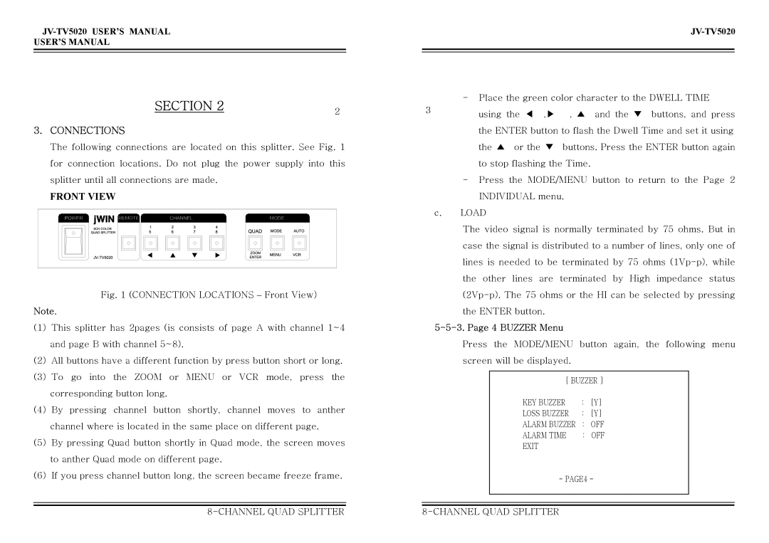
The following connections are located on this splitter. See Fig. 1 for connection locations. Do not plug the power supply into this splitter until all connections are made.
FRONT VIEW
Fig. 1 (CONNECTION LOCATIONS – Front View)
Note.
(1)This splitter has 2pages (is consists of page A with channel 1~4 and page B with channel 5~8).
(2)All buttons have a different function by press button short or long.
(3)To go into the ZOOM or MENU or VCR mode, press the corresponding button long.
(4)By pressing channel button shortly, channel moves to anther channel where is located in the same place on different page.
(5)By pressing Quad button shortly in Quad mode, the screen moves to anther Quad mode on different page.
(6)If you press channel button long, the screen became freeze frame.
-Place the green color character to the DWELL TIME
3 | using the ◀ ,▶ | , ▲ and the ▼ buttons, and press |
| ||
| the ENTER button to flash the Dwell Time and set it using | |
| the ▲ or the ▼ | buttons. Press the ENTER button again |
| to stop flashing the Time. | |
-Press the MODE/MENU button to return to the Page 2 INDIVIDUAL menu.
c.LOAD
The video signal is normally terminated by 75 ohms. But in case the signal is distributed to a number of lines, only one of lines is needed to be terminated by 75 ohms
5-5-3. Page 4 BUZZER Menu
Press the MODE/MENU button again, the following menu screen will be displayed.
[ BUZZER ]
KEY BUZZER | : | [Y] |
LOSS BUZZER | : | [Y] |
ALARM BUZZER | : | OFF |
ALARM TIME | : | OFF |
EXIT |
|
|
- PAGE4 -
