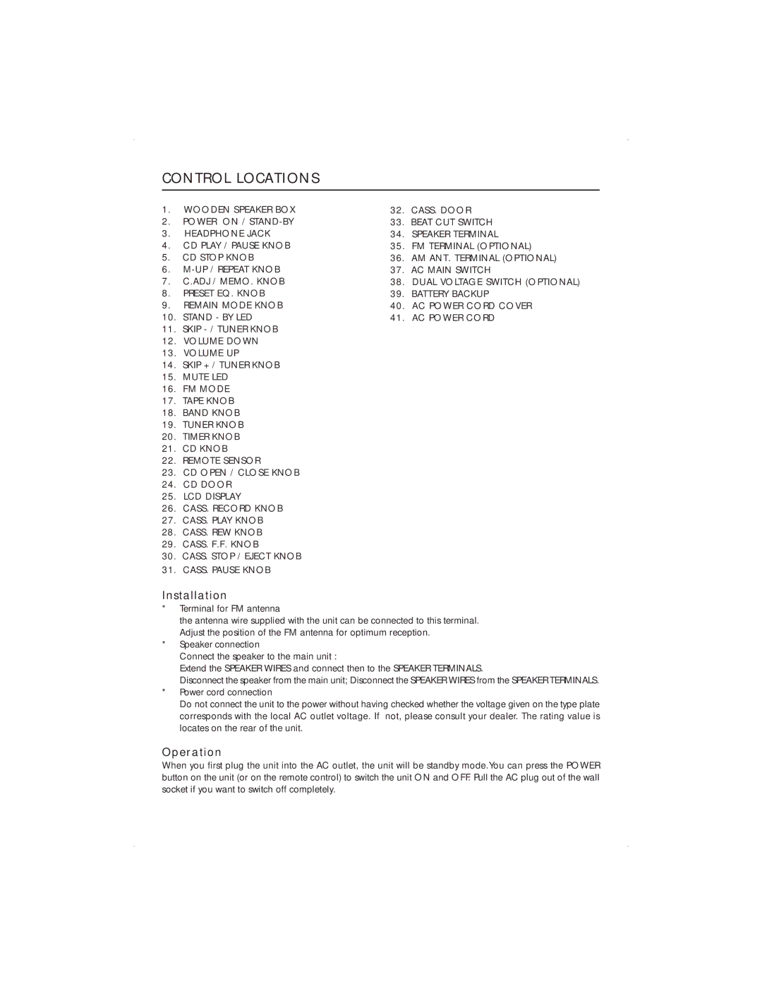
CONTROL LOCATIONS
1.WOODEN SPEAKER BOX
2.POWER ON /
3.HEADPHONE JACK
4.CD PLAY / PAUSE KNOB
5.CD STOP KNOB
6.
7.C.ADJ / MEMO. KNOB
8.PRESET EQ. KNOB
9.REMAIN MODE KNOB
10.STAND - BY LED
11.SKIP
12.VOLUME DOWN
13.VOLUME UP
14.SKIP +/ TUNER KNOB
15.MUTE LED
16.FM MODE
17.TAPE KNOB
18.BAND KNOB
19.TUNER KNOB
20.TIMER KNOB
21.CD KNOB
22.REMOTE SENSOR
23.CD OPEN / CLOSE KNOB
24.CD DOOR
25.LCD DISPLAY
26.CASS. RECORD KNOB
27.CASS. PLAY KNOB
28.CASS. REW KNOB
29.CASS. F.F. KNOB
30.CASS. STOP / EJECT KNOB
31.CASS. PAUSE KNOB
32.CASS. DOOR
33.BEAT CUT SWITCH
34.SPEAKER TERMINAL
35.FM TERMINAL (OPTIONAL)
36.AM ANT. TERMINAL (OPTIONAL)
37.AC MAIN SWITCH
38.DUAL VOLTAGE SWITCH (OPTIONAL)
39.BATTERY BACKUP
40.AC POWER CORD COVER
41.AC POWER CORD
Installation
*Terminal for FM antenna
the antenna wire supplied with the unit can be connected to this terminal. Adjust the position of the FM antenna for optimum reception.
*Speaker connection
Connect the speaker to the main unit :
Extend the SPEAKER WIRES and connect then to the SPEAKER TERMINALS.
Disconnect the speaker from the main unit; Disconnect the SPEAKER WIRES from the SPEAKER TERMINALS.
*Power cord connection
Do not connect the unit to the power without having checked whether the voltage given on the type plate corresponds with the local AC outlet voltage. If not, please consult your dealer. The rating value is locates on the rear of the unit.
Operation
When you first plug the unit into the AC outlet, the unit will be standby mode.You can press the POWER button on the unit (or on the remote control) to switch the unit ON and OFF. Pull the AC plug out of the wall socket if you want to switch off completely.
