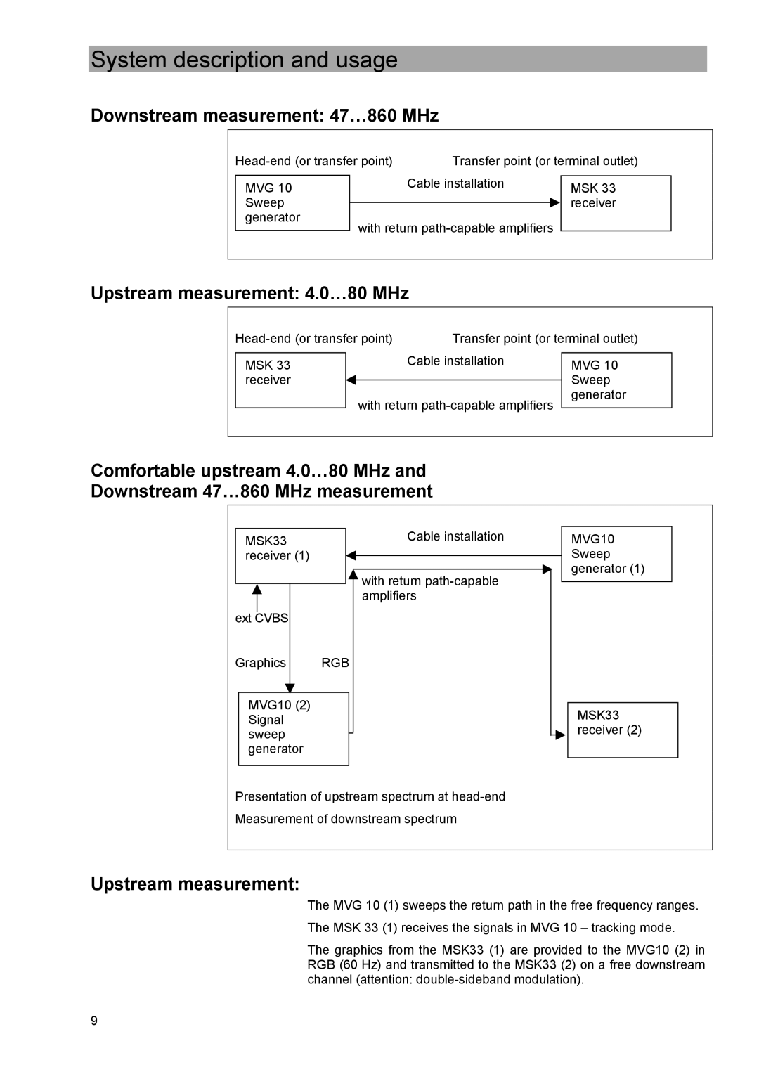
MVG 10 specifications
The Kathrein MVG 10 is a state-of-the-art measurement system designed for the analysis and optimization of modern mobile communication networks. Tailored for telecommunications engineers and network operators, the MVG 10 stands out due to its advanced features, superior technologies, and overall performance.One of the main features of the Kathrein MVG 10 is its versatility in supporting multiple frequency bands. This measurement device is capable of analyzing frequency ranges from 10 MHz up to 6 GHz, making it suitable for a wide array of wireless communication standards including LTE, 5G, and Wi-Fi. This broad frequency support allows network operators to conduct comprehensive network assessments across different technologies, ensuring optimum performance in mixed environments.
The MVG 10 is equipped with state-of-the-art software tools that provide user-friendly interfaces for network analysis. The intuitive graphical display allows for the easy monitoring of key performance indicators such as signal strength, signal quality, and interference levels. Real-time data visualization enables engineers to identify issues quickly and make informed decisions, which is essential for maintaining high-quality network services.
In addition to its impressive frequency capabilities, the Kathrein MVG 10 features advanced measurement technologies such as MIMO (Multiple Input Multiple Output) capabilities. This allows for the analysis of spatial diversity in signal reception, essential for modern communication systems that rely on multiple antennas to enhance data throughput and reliability.
Moreover, the device supports geolocation features, enabling operators to pinpoint the location of specific transmission issues or user complaints effectively. This functionality not only increases the accuracy of network testing but also significantly reduces the time required for troubleshooting.
The compact and portable design of the MVG 10 ensures convenience for field engineers who need to perform measurements on-site. Its robust construction is built to withstand challenging environments, ensuring durability while maintaining high precision during measurements.
Overall, the Kathrein MVG 10 is an essential tool for telecommunications professionals. Its combination of versatile frequency support, advanced measurement technologies, and user-friendly features makes it an invaluable asset for optimizing mobile communication networks and delivering high-quality services to end users. In an era where connectivity is paramount, the MVG 10 stands out as a reliable solution for the demands of today's fast-paced telecommunications landscape.

