FUNCTIONAL DESCRIPTION
LOCATION
2
1
Position the Arc Welder on a secure level surface in a dry location where there is free circulation of clean air. Ensure all air passages are clean and free of obstruc-
3
4
5
6
15 ![]()
|
|
| 8 |
|
|
| 10 | 7 | 14 |
|
|
| ||
|
|
|
| |
| 9 |
|
|
|
|
| 11 | 13 |
|
|
|
|
| |
|
|
| 12 |
|
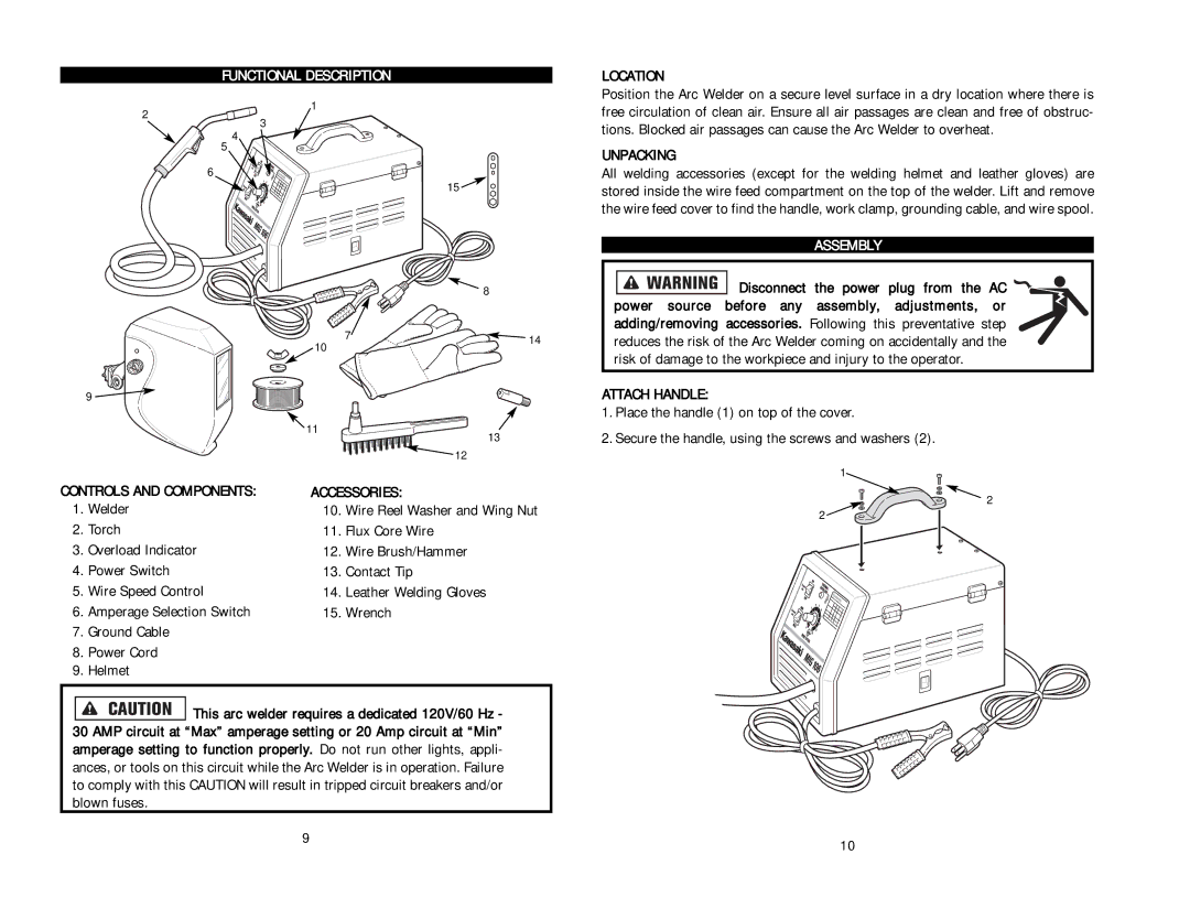
CONTROLS AND COMPONENTS: | ACCESSORIES: |
| ||
1. | Welder | 10. | Wire Reel Washer and Wing Nut | |
2. | Torch | 11. | Flux Core Wire |
|
3. | Overload Indicator | 12. | Wire Brush/Hammer |
|
4. | Power Switch | 13. | Contact Tip |
|
5. | Wire Speed Control | 14. | Leather Welding Gloves |
|
6. | Amperage Selection Switch | 15. | Wrench |
|
7.Ground Cable
8.Power Cord
9.Helmet
![]()
![]()
![]()
![]()
![]()
![]()
![]() This arc welder requires a dedicated 120V/60 Hz - 30 AMP circuit at “Max” amperage setting or 20 Amp circuit at “Min” amperage setting to function properly. Do not run other lights, appli- ances, or tools on this circuit while the Arc Welder is in operation. Failure to comply with this CAUTION will result in tripped circuit breakers and/or blown fuses.
This arc welder requires a dedicated 120V/60 Hz - 30 AMP circuit at “Max” amperage setting or 20 Amp circuit at “Min” amperage setting to function properly. Do not run other lights, appli- ances, or tools on this circuit while the Arc Welder is in operation. Failure to comply with this CAUTION will result in tripped circuit breakers and/or blown fuses.
tions. Blocked air passages can cause the Arc Welder to overheat.
UNPACKING
All welding accessories (except for the welding helmet and leather gloves) are stored inside the wire feed compartment on the top of the welder. Lift and remove the wire feed cover to find the handle, work clamp, grounding cable, and wire spool.
ASSEMBLY
![]()
![]()
![]()
![]()
![]()
![]()
![]() Disconnect the power plug from the AC power source before any assembly, adjustments, or adding/removing accessories. Following this preventative step reduces the risk of the Arc Welder coming on accidentally and the risk of damage to the workpiece and injury to the operator.
Disconnect the power plug from the AC power source before any assembly, adjustments, or adding/removing accessories. Following this preventative step reduces the risk of the Arc Welder coming on accidentally and the risk of damage to the workpiece and injury to the operator.
ATTACH HANDLE:
1.Place the handle (1) on top of the cover.
2.Secure the handle, using the screws and washers (2).
1
![]()
![]() 2 2
2 2 ![]()
![]()
9 | 10 |
|