POSITIONING
CLEARANCES
| Combustible | |
| Construction | Construction |
Back | 6" | 0" |
|
|
|
Right Side | 6" | 0" |
|
|
|
Left Side | 6" | 0" |
|
|
|
The pasta cooker must be no closer than 6" from any combustible material. When placed under an exhaust hood with a fire retardant system it must comply with ANSI/UL
RESTRAINING DEVICES
![]() WARNING
WARNING
Restraining devices
required.
On Custom Pasta™ System installations with casters, casters and jam nuts must be completely tightened. Adequate means must also be provided to limit the movement of the appliance without depending on the connector, the
the appliance movement.
(Latest Edition). No frame or restriction can be constructed around the lower part of the pasta cooker that would restrict ventilation or air movement into the pasta cooker. You must insure adequate air supply to the pasta cooker.
Adequate clearance for servicing and proper operation must be maintained. Your pasta cooker is designed to be serviced from the front. Do not place a pasta cooker next to a deep fat fryer. Hot oil and water can cause an unstable condition creating a hazardous situation. The pasta cooker will operate at highest efficiency when properly leveled. Place a level across the cooker front panel from left to right, and then front to rear. Screw the adjustable bullet feet or casters in or out as necessary until the cooker is as level as possible. Each leg is adjustable to 3/4". Do not expose more than three threads on the stem of the caster.
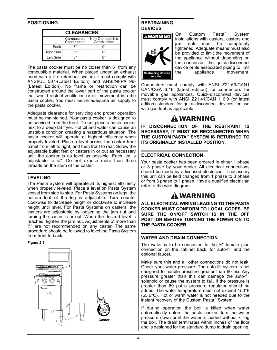
LEVELING
The Pasta System will operate at its highest efficiency when properly leveled. Place a level on Pasta System vessel from side to side. For Pasta Systems on legs, the bottom foot of the leg is adjustable. Turn counter clockwise to decrease height or clockwise to increase height until level. For Pasta Systems on casters, the casters are adjustable by loosening the jam nut and turning the caster in or out. When the desired level is reached, tighten the jam nut. Adjustments of more than
3/4" are not recommended on any caster. The same procedure should be followed to level the Pasta System from front to back.
Figure
Caster
Connectors must comply with ANSI Z21.69/CAN1 CAN/CGA 6.16 (latest edition) for connectors for movable gas appliances.
IF DISCONNECTION OF THE RESTRAINT IS NECESSARY, IT MUST BE RECONNECTED WHEN THE CUSTOM PASTA™ SYSTEM IS RETURNED TO ITS ORIGINALLY INSTALLED POSITION.
ELECTRICAL CONNECTION
Your pasta cooker has been ordered in either 1 phase or 3 phase by your dealer. All electrical connections should be made by a licensed electrician. If necessary this unit can be field changed from 1 phase to 3 phase or from 3 phase to 1 phase. Have a qualified electrician refer to the wire diagram.
ALL ELECTRICAL WIRING LEADING TO THE PASTA COOKER MUST CONFORM TO LOCAL CODES. BE SURE THE ON/OFF SWITCH IS IN THE OFF POSITION BEFORE TURNING THE POWER ON TO THE PASTA COOKER.
WATER AND DRAIN CONNECTION
The water is to be connected to the 3/8" female pipe connection on the cabinet back, for
Make sure this and all other connections do not leak. Check your water pressure. The
If during operation the boil is killed when water automatically enters the pasta cooker, turn the water pressure down until the water is added without killing the boil. The drain terminates within inches of the floor and is designed for the standard dump to drain opening.
4