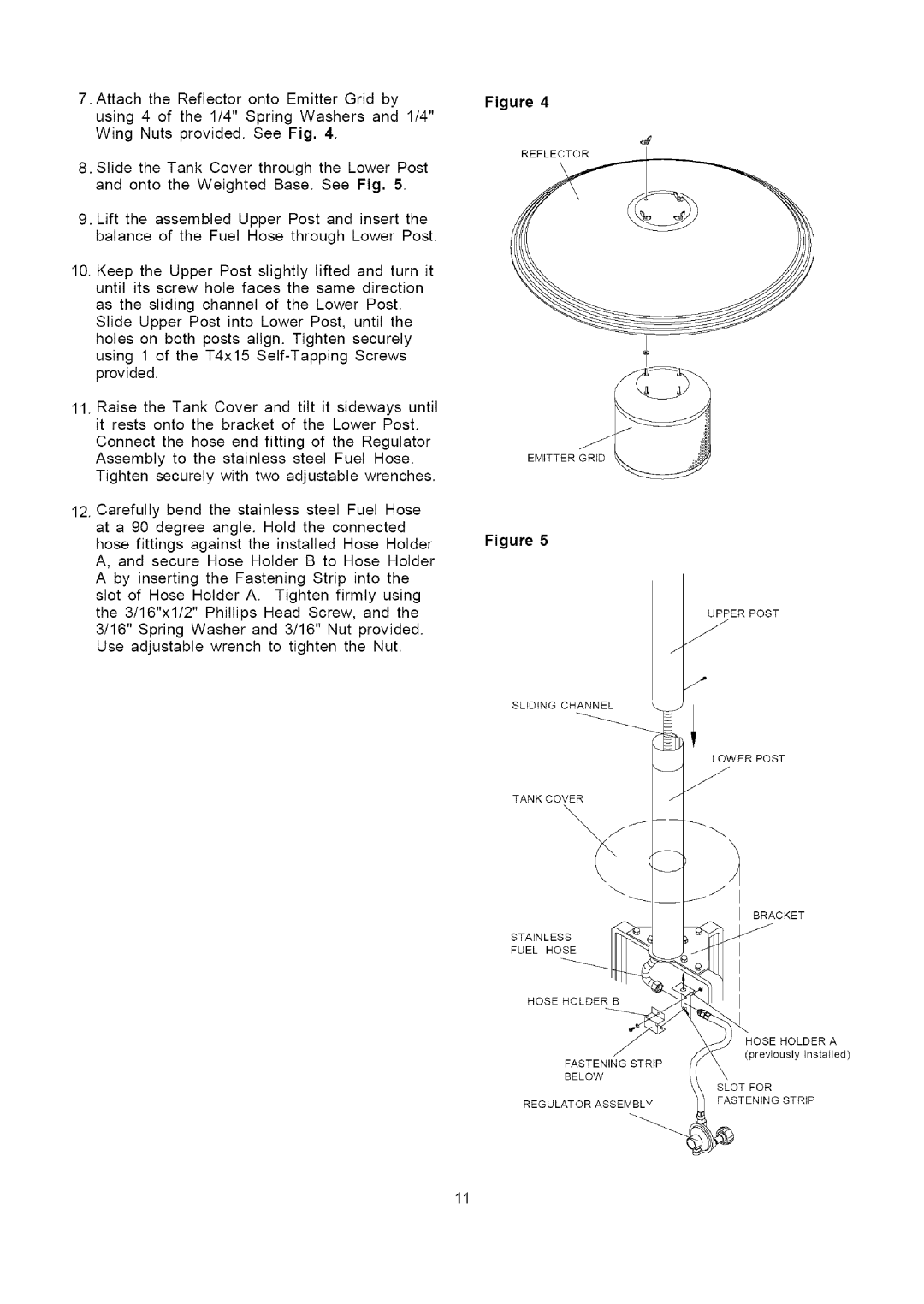
7.Attachthe Reflectoronto EmitterGridby using4 of the 1/4" SpringWashersand 1/4" Wing Nutsprovided.See Fig. 4.
8.SlidetheTankCoverthroughthe LowerPost and onto the WeightedBase.See Fig. 5.
9.Lift the assembled Upper Post and insert the
balance of the Fuel Hose through Lower Post.
10.Keep the Upper Post slightly lifted and turn it until its screw hole faces the same direction
as the sliding channel of the Lower Post. Slide Upper Post into Lower Post, until the holes on both posts align. Tighten securely using 1 of the T4x15
11.Raise the Tank Cover and tilt it sideways until it rests onto the bracket of the Lower Post.
Connect the hose end fitting of the Regulator Assembly to the stainless steel Fuel Hose. Tighten securely with two adjustable wrenches.
12.Carefully bend the stainless steel Fuel Hose
at a 90 degree angle. Hold the connected hose fittings against the installed Hose Holder A, and secure Hose Holder B to Hose Holder A by inserting the Fastening Strip into the slot of Hose Holder A. Tighten firmly using the 3/16"xl/2" Phillips Head Screw, and the 3/16" Spring Washer and 3/16" Nut provided. Use adjustable wrench to tighten the Nut.
Figure 4
EMITTER
Figure 5
UPPER POST
f"
SLIDING CHANNEL
LOWER POST
TANK COVER
jJ
BRACKET
I
STAINLESS
FUEL HOSE
HOSE HOLDER B
HOSE HOLDER A
(previouslyinstalled)
FASTENING STRIP
BELOW
SLOT FOR
REGULATOR ASSEMBLY
FASTENING STRIP
11