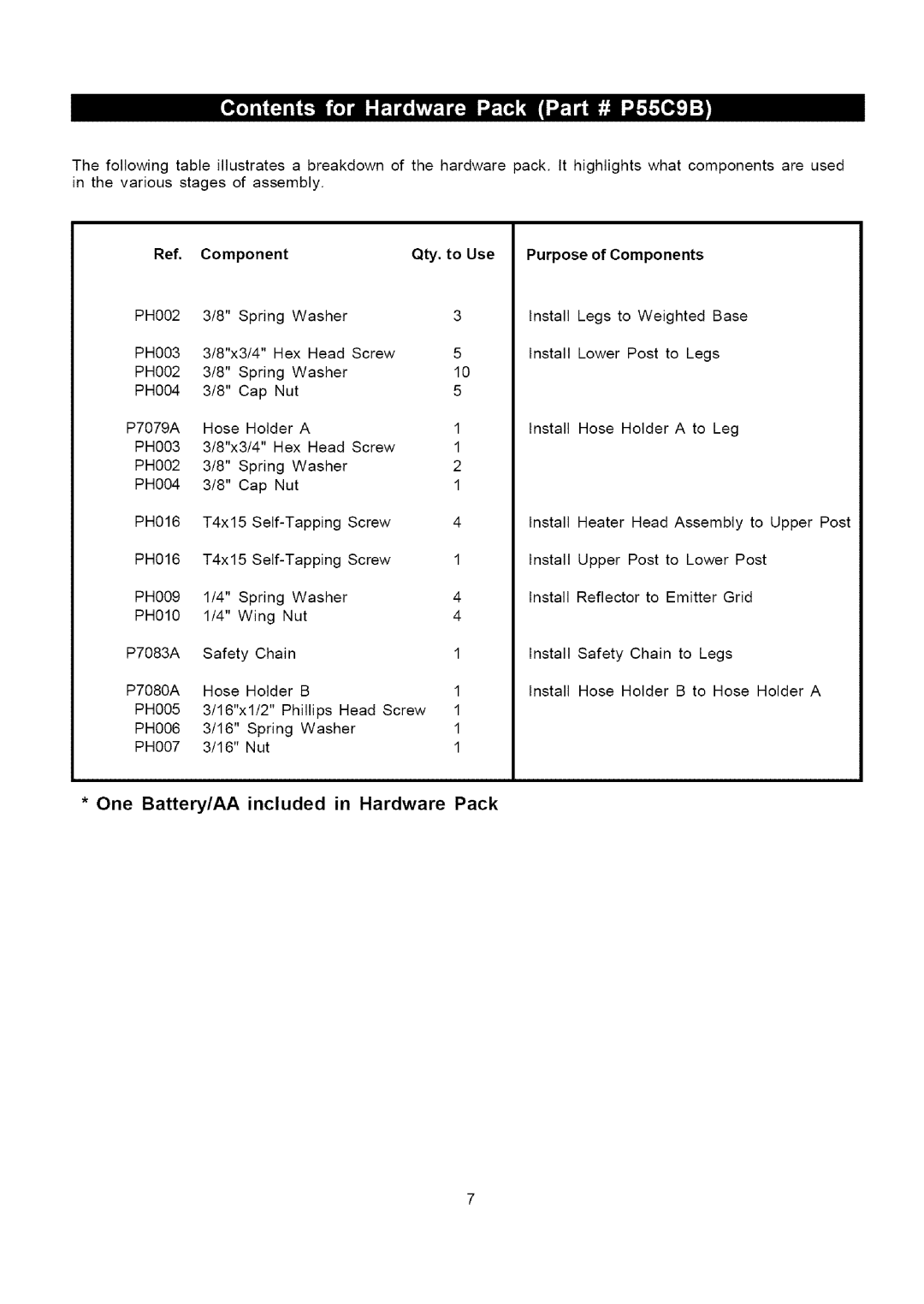
The following table illustrates a breakdown of the hardware pack. It highlights what components are used in the various stages of assembly.
Ref. | Component |
|
| Qty. to Use | Purpose of Components |
|
|
| ||||||||
PH002 | 3/8" | Spring | Washer |
|
| 3 | Install | Legs | to Weighted | Base |
|
| ||||
PH003 | 3/8"x3/4" | Hex Head | Screw |
| 5 | Install | Lower | Post to Legs |
|
| ||||||
PH002 | 3/8" | Spring | Washer |
|
| 10 |
|
|
|
|
|
|
|
| ||
PH004 | 3/8" | Cap | Nut |
|
| 5 |
|
|
|
|
|
|
|
| ||
P7079A | Hose |
| Holder | A |
|
| 1 | Install | Hose | Holder | A to | Leg |
|
| ||
PH003 | 3/8"x3/4" | Hex Head | Screw |
| 1 |
|
|
|
|
|
|
|
| |||
PH002 | 3/8" | Spring | Washer |
|
| 2 |
|
|
|
|
|
|
|
| ||
PH004 | 3/8" | Cap | Nut |
|
| 1 |
|
|
|
|
|
|
|
| ||
PH016 | T4x15 | Screw |
| 4 | Install | Heater | Head | Assembly | to Upper | Post | ||||||
PH016 | T4x15 | Screw |
| 1 | Install | Upper Post to Lower Post |
| |||||||||
PH009 | 1/4" | Spring | Washer |
|
| 4 | Install | Reflector | to | Emitter | Grid |
|
| |||
PH010 | 1/4" | Wing | Nut |
|
| 4 |
|
|
|
|
|
|
|
| ||
P7083A | Safety | Chain |
|
|
| 1 | Install Safety Chain to Legs |
|
| |||||||
P7080A | Hose |
| Holder | B |
|
| 1 | Install | Hose | Holder | B to | Hose | Holder | A | ||
PH005 | 3/16"x1/2" | Phillips Head Screw | 1 |
|
|
|
|
|
|
|
| |||||
PH006 | 3/16" |
| Spring | Washer |
|
| 1 |
|
|
|
|
|
|
|
| |
PH007 | 3/16" |
| Nut |
|
|
|
| 1 |
|
|
|
|
|
|
|
|
