Installation Instructions (cont'd)
Venting (cont'd)
All vent gases must be completely vented to the outdoors of the
structure (dwelling). install only the draft hood provided with the new water heater and no other draft hood.
Vent pipes must be secured at each joint with sheet metal screws.
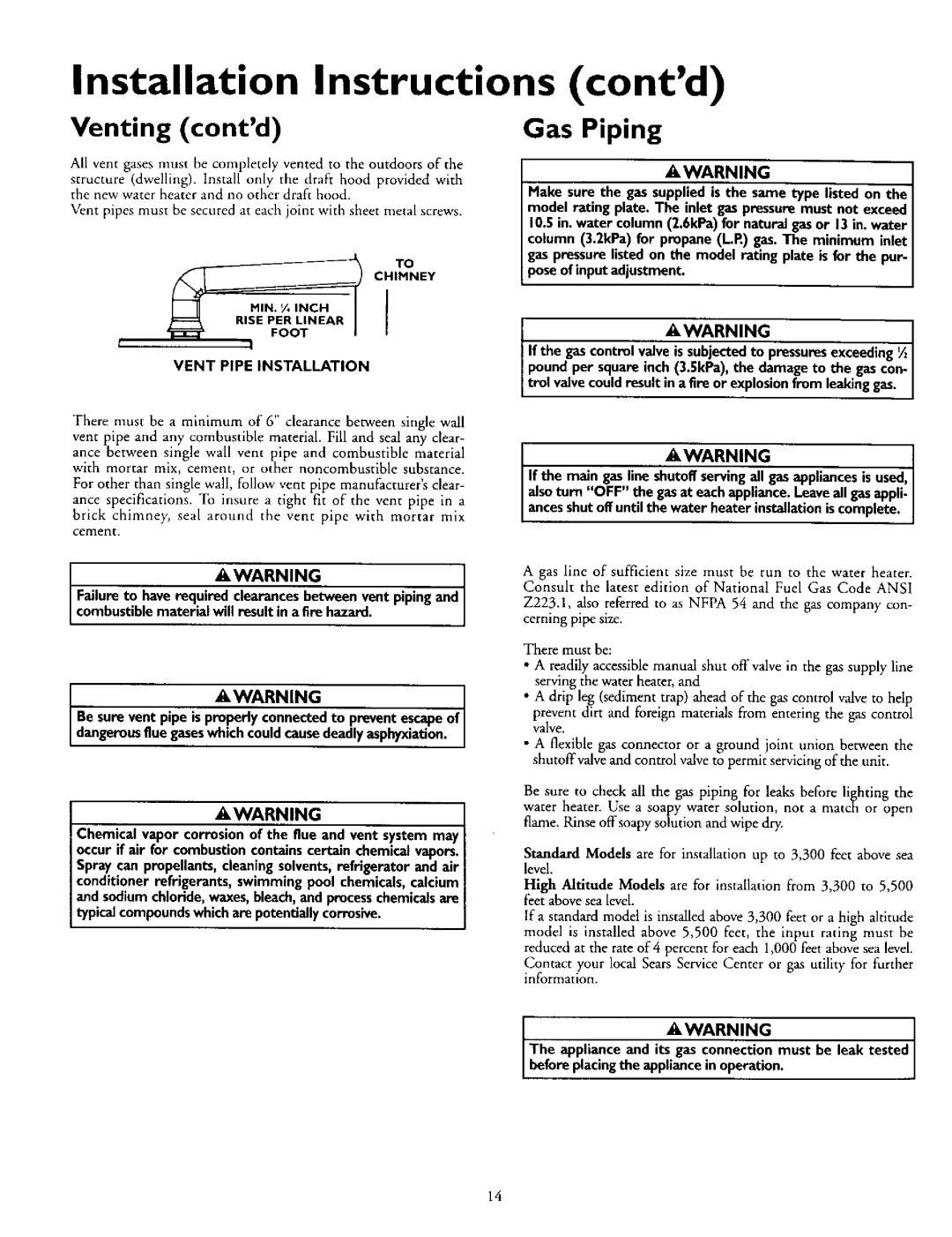
TO
CHIMNEY
!
VENT PIPE INSTALLATION
There must be a minimum of 6" clearance between single wall vent pipe and any combustible material. Fill and seal any clear-
ance between single wall vent pipe and combustible material with mortar mix, cement, or other noncombustible substance.
For other than single wall, follow vent pipe manufacturer's clear- ance specifications. To insure a tight fit of the vent pipe in a
brick chimney, seal around the vent pipe with mortar mix cement.
AWARNING
Failureto haverequired clearancesbetween vent pipingand combustiblematerial will result in a fire hazard.
AWARNING]
Be sure vent pipe ispropody connectedto preventescapeof I dangerousflue gaseswhichcouldcausedeadlyasphyxiation. ]
AWARNING
Chemical vapor corrosionof the flue and vent system may occurif air for combustioncontainscertain chemicalvapors. Spray can propellants,cleaningsolvents,refrigerator and air conditioner refrigerants, swimming pool chemicals,calcium and sodiumchloride,waxes,bleach,and processchemicalsare typicalcompoundswhichare potentiallycorrosive.
Gas Piping
AWARNING
Make sure the gassupplied is the same type listed on the model rating plate. The inlet gaspressuremust not exceed 10.5in. water column (2.6kPa)for natural gasor 13in. water column (3.2kPa) for propane (L.P.)gas.The minimum inlet
gaspressurelistedon the model rating plate is for the pur- poseof input adjustment.
AWARNING,
If the gascontrolvalveis subjectedto pressuresexceeding'A poundper squareinch(3.5kPa), the damage to the gascon-
trol valvecouldresult in a fire or explosionfrom leakinggas.
_WARNING
If the main gasline shutoffservingall gasappliancesisused, alsoturn "OFF" the gasat eachappliance. Leaveall gasappli.
ancesshutoff untilthe water heater installationiscomplete.
A gas line of sufficient size must be run to the water heater. Consult the latest edition of National Fuel Gas Code ANSI
Z223.1, also referred to as NFPA 54 and the gas company con- cerning pipe size.
There must be:
•A readily accessible manual shut offvalve in the gas supply llne serving the water heater, and
•A drip leg (sediment trap) ahead of the gas control valve to help
prevent dirt and foreign materials from entering the gas control valve.
•A flexible gas connector or a ground joint union between the shutoffvalve and control valve to permit servicing of the unit.
Be sure to check all the gas piping for leaks before lil_hting the water heater. Use a soapy water solution, not a match or open
flame. Rinse offsoapy solution and wipe dry.
Standard Models are for installation up to 3,300 feet above sea level.
High Altitude Models are for installation from 3,300 to 5,500 feet above sea level.
If a standard model is installed above 3,300 feet or a high altitude model is installed above 5,500 feet, the input rating must he
reduced at the rate of 4 percent for each 1,000 feet above sea level.
Contact your local Sears Service Center or gas utility for further information.
f | AWARNING |
|
| The applianceand it_ | must be leak tested |
| beforeplacingthe appliance in operation. | |
14