Combustion Air and Ventilation for
Appliances Located in Confined Spaces
CONFINED SPACE is a space whose volume is less than 50 cubic feet per 1,000 Btu per hour (4.8 m 3 per kW) of the aggregate input rating of all appliances installed in that space.
A.ALL AIR FROM INSIDE BUILDINGS:
(See Figure 9 on page 9 and Figure 10 below)
The confined space shah be provided with two permanent openings communicating directly with an additional room(s) of sufficient volume so that the combined volume of all spaces meets the criteria for an unconfined space. The total input of all gas utilization equipment installed in the combined space
shall be considered in making this determination. Each opening shall have a minimum free area of one square inch per 1,000 Btu per hour (22 cm_/kW) of the total input rating of all gas utilization equipment in the confined space, but not less than 100 square inches (645 cm2). One opening shall commence within 12 inches (30 cm) of the top and one
commencing within 12 inches (30 cm) of the bottom of the enclosures.
NT
FUR__ | NG |
FIGURE10.
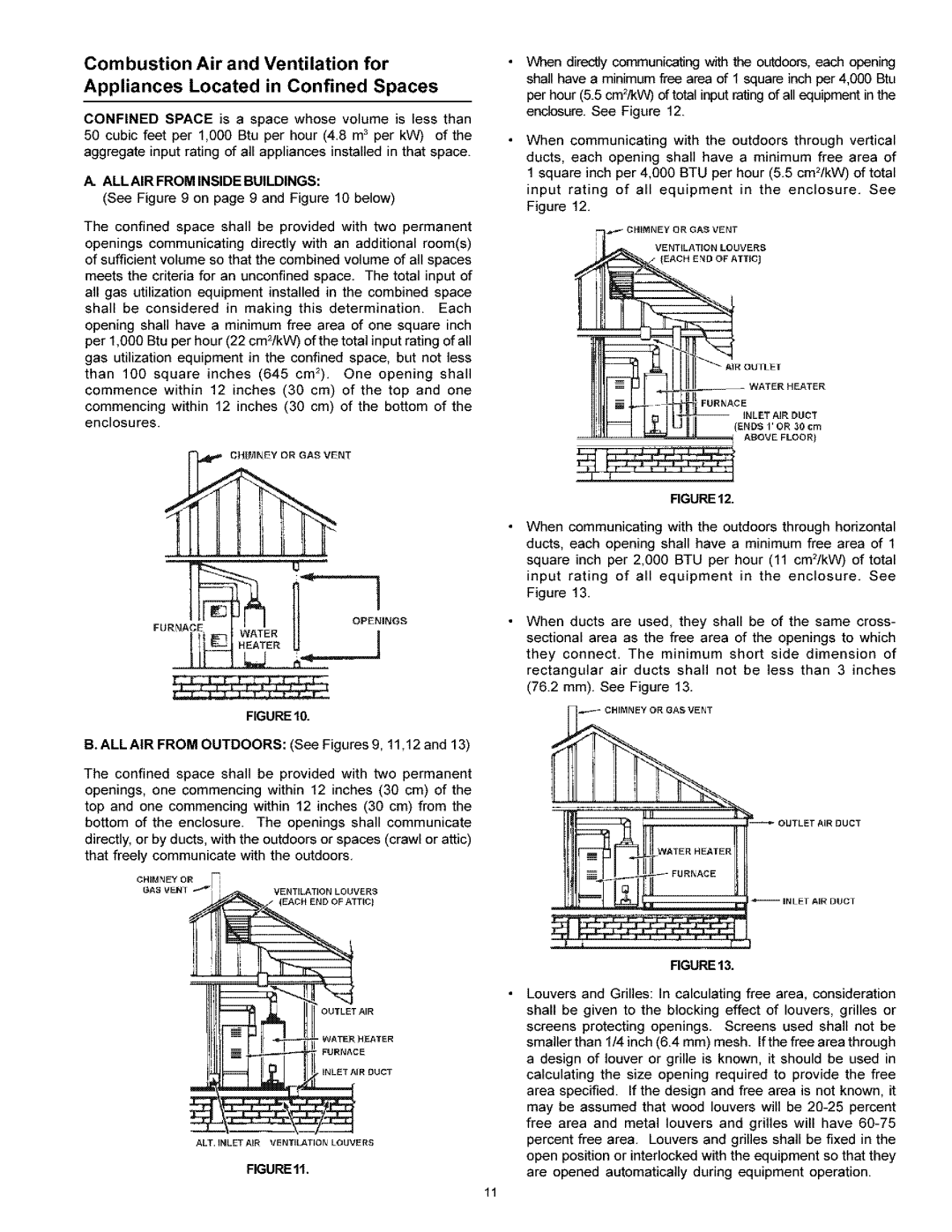
B. ALL AIR FROM OUTDOORS: (See Figures 9, 11,12 and 13)
The confined space shall be provided with two permanent openings, one commencing within 12 inches (30 cm) of the top and one commencing within 12 inches (30 cm) from the bottom of the enclosure. The openings shall communicate directly, or by ducts, with the outdoors or spaces (crawl or attic) that freely communicate with the outdoors.
CHIMNEY OR |
|
|
GAS VENT | VENTILATION | LOUVERS |
| IEACH END | OF ATTIC) |
OUTLET AIR
WATER HEATER
FURNACE
INLET AIR DUCT
ALT. INLET AIR VENTII ATION LOUVERS
FIGUREll.
When directly communicating with the oL_doors, each opening shall have a minimum free area of 1 square inch per 4,000 Btu per hour (5.5 cm2/kW) of total input rating of all equipment in the enclosure. See Figure 12.
When communicating with the outdoors through vertical
ducts, each opening shall have a minimum free area of 1 square inch per 4,000 BTU per hour (5.5 cm2/kW) of total
input rating of all equipment in the enclosure. See Figure 12.
VENTILATION LOUVERS
FURNACE
INLET AIR DUCT
(ENDS 1'OR 30 cm
ABOVE FLOOR)
FIGURE12.
When communicating with the outdoors through horizontal ducts, each opening shall have a minimum free area of 1 square inch per 2,000 BTU per hour (11 cm2/kW) of total
input rating of all equipment in the enclosure. See Figure 13.
When ducts are used, they shall be of the same cross- sectional area as the free area of the openings to which they connect. The minimum short side dimension of rectangular air ducts shall not be less than 3 inches (76.2 mm). See Figure 13.
____ CHIMNEY OR GAS VENT
OUTLET AIR DUCT
iNLET AIR DUCT
FIGURE 13.
Louvers and Grilles: in calculating free area, considerafion shall be given to the blocking effect of louvers, grilles or screens protecting openings. Screens used shall not be smaller than 1/4 inch (6.4 mm) mesh. If the free area through a design of louver or grille is known, it should be used in calculating the size opening required to provide the free area specified. If the design and free area is not known, it may be assumed that wood louvers will be
11