Connecting Wires to Terminals
English
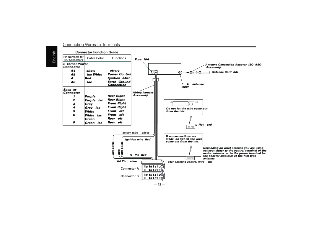
Connector Function Guide
Pin Numbers for | Cable Color | Functions | |
ISO Connectors | |||
|
| ||
External Power |
|
| |
Connector |
| Battery | |
Yellow | |||
Blue/White | Power Control | ||
Red | Ignition (ACC) | ||
Black | Earth (Ground) | ||
|
| Connection | |
Speaker |
|
| |
Connector |
| Rear Right (+) | |
Purple | |||
Purple/Black | Rear Right | ||
Gray | Front Right (+) | ||
Gray/Black | Front Right | ||
White | Front Left (+) | ||
White/Black | Front Left | ||
Green | Rear Left (+) | ||
Green/Black | Rear Left | ||
|
|
|
Fuse (10A) 13
Wiring harness (Accessory1) 16
Antenna Conversion Adaptor
![]() Antenna Cord (ISO) 1
Antenna Cord (ISO) 1
FM/AM antenna input 3
Do not let the wire come out from the tab.
Not Used
TEL MUTE
Battery wire (Yellow) 6
Ignition wire (Red) 7
If no connections are made, do not let the wire come out from the tab. 18
ANT CONT
Depending on what antenna you are using, connect either to the control terminal of the motor antenna, or to the power terminal for the booster amplifier of the
![]() Motor antenna control wire (Blue)
Motor antenna control wire (Blue)
Connector A | 8 | 6 | 4 | 2 | |
7 | 5 | 3 | 1 | ||
|
Connector B | 8 | 6 | 4 | 2 | |
7 | 5 | 3 | 1 | ||
|
— 12 —