Mediant 2000 & TP-1610 SIP User’s Manual
Page
Table of Contents
139
135
BootP/DHCP Support 167
Diagnostics 165
SNMP-Based Management 171
201
183
187
189
Appendix M Regulatory Information
Appendix J SS7 Tunneling
Appendix K Radius Billing and Vxml Calling Card Application
Appendix L Snmp Traps 271
List of Figures
168
List of Tables
272
Related Documentation
Trademarks
Customer Support
Abbreviations and Terminology
Overview
T1 Available Configurations
Available Configurations
Service Node
E1 Available Configurations
SIP Overview
Mediant 2000 Features
General Features
Hardware Features
Supported Interworking Features
Supported SIP Features
PSTN-to-SIP Interworking
Mediant 2000 SIP User’s Manual Overview
Reader’s Notes
Component Description
General
Label
Mediant 2000 Chassis
Power Supply
TP-1610 Board
Electrical Component Sensitivity
Board Hot-Swap Support
Mediant 2000 SIP
2 TP-1610 Front Panel LED Indicators
Rear Transition Module
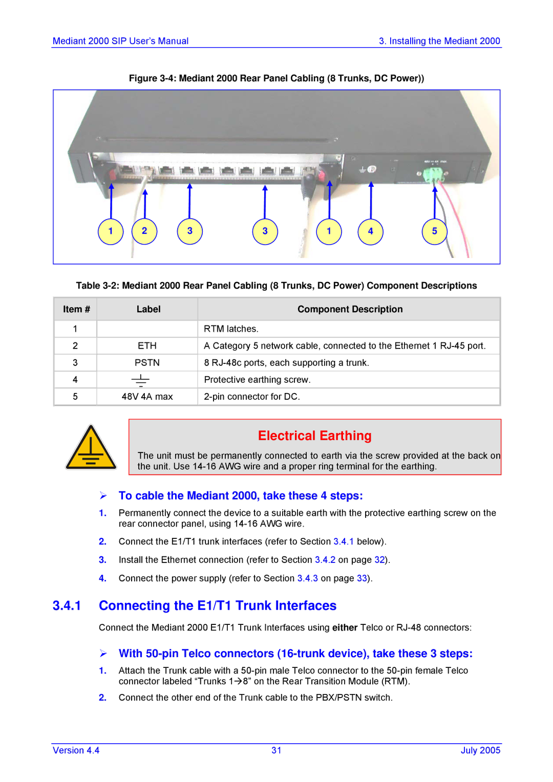
Rear Panel with two 50-pin Connectors for 16 Trunks
Optional CPU Board
Reader’s Notes
Unpacking
Package Contents
To attach the two front side brackets, take these 3 steps
Installing the Mediant 2000 in a 19-inch Rack
Mounting the Mediant
Mounting the Mediant 2000 on a Desktop
Mediant 2000 Front View with 19-inch Rack Mount Brackets
To attach the device to a 19-inch rack, take these 2 steps
Item # Label
Cabling the Mediant
To cable the Mediant 2000, take these 4 steps
Connecting the E1/T1 Trunk Interfaces
E1/T1 Number Tx Pins Tip/Ring Rx Pins Tip/Ring
Installing the Ethernet Connection
With RJ-48c Connectors, take these 2 steps
E1/T1 Connections on each 50-pin Telco Connector
When using a dual AC power cable
Connecting the Power Supply
Connecting the DC Power Supply
DC Terminal Block Screw Connector
To assign an IP address using HTTP, take these 9 steps
Assigning an IP Address Using Http
Assigning the Mediant 2000 IP Address
To assign an IP address using BootP, take these 4 steps
Assigning an IP Address Using BootP
Restoring Networking Parameters to their Initial State
To configure basic SIP parameters, take these 10 steps
Configuring the Mediant 2000 Basic Parameters
Mediant 2000 SIP
Overview of the Embedded Web Server
Configuration Concepts
Computer Requirements
Limiting the Embedded Web Server to Read-Only Mode
Password Control
Configuring the Web Interface via the ini File
Embedded Web Server Username & Password
Unauthorized
Accessing the Embedded Web Server
Using Internet Explorer to Access the Embedded Web Server
To access the Embedded Web Server, take these 4 steps
Main Menu Bar
Getting Acquainted with the Web Interface
Entering Phone Numbers in Various Tables
Saving Changes
To save the changes to flash, take these 2 steps
Coders
To configure the gateway’s coders, take these 6 steps
Protocol Management
Protocol Definition Parameters
Number Manipulation Tables
Advanced Parameters
Number Manipulation Parameters Description
Source Phone Number Manipulation Table for Tel IP Calls
Number of digits to leave Prefix / suffix to add
Dialing Plan Notation
NPI/TON Values for Isdn Etsi
Numbering Plans and Type of Number
Description
Tel to IP Routing Table
Configuring the Routing Tables
To configure the Tel to IP Routing table, take these 6 steps
Tel to IP Routing Table Parameter Description
IP to Trunk Group Routing Table
Parameter Description
IP to Trunk Group Routing Table
Internal DNS Table
To configure the internal DNS table, take these 7 steps
IP to Trunk Group Routing Table Parameter Description
You can use this table for example
Reasons for Alternative Routing
Coder Group Settings
Configuring the Profile Definitions
To configure the coder group settings, take these 8 steps
To configure the Tel Profile settings, take these 8 steps
Tel Profile Settings
To configure the IP Profile settings, take these 8 steps
IP Profile Settings
To configure the Trunk Group table, take these 4 steps
Configuring the Trunk Group Table
Channel or channels that correspond to the trunk group ID
Trunk Group Table Parameter Description
13 Trunk Group Settings Screen
Configuring the Trunk Group Settings
Channel Select Modes
Mode Description
Configuring the Network Settings
Advanced Configuration
Simple Network Time Protocol Support
Configuring the Snmp Managers Table
To configure the Snmp Managers Table, take these 6 steps
Multiple Routers Support
Mediant 2000 SIP
16 Channel Settings Screen
Configuring the Channel Settings
To configure the Trunk Settings, take these 9 steps
Configuring the Trunk Settings
Trunks Status Color Indicator Keys
18TDM Bus Settings Screen
Configuring the TDM Bus Settings
To back up the ini file, take these 4 steps
Restoring and Backing up the Gateway Configuration
To restore or back up the ini file
To restore the ini file, take these 4 steps
20 Regional Settings Screen
Regional Settings
Gateway Statistics
Status & Diagnostic
Changing the Mediant 2000 Username and Password
To change the username and password, take these 5 steps
To view the IP connectivity information, take these 2 steps
Quality Info
Call Counters
To view the IP Tel and Tel IP Call Counters information
IP Connectivity Parameters Column Name Description
Gwappreasonnotrelevant
24 Mediant 2000 Trunk & Channel Status Screen
Monitoring the Mediant 2000 Trunks & Channels
To activate the Message Log, take these 4 steps
Activating the Internal Syslog Viewer
System Information
To access the System Information screen
Software Upgrade Wizard
Software Update Menu
To use the Software Upgrade Wizard, take these 9 steps
30 Load a cmp File Screen
32 Load an ini File Screen
Cancel
Reset
Voice Prompts
Auxiliary Files
10 Auxiliary Files Descriptions
File Type Description
36 Auxiliary Files Screen
Updating the Software Upgrade Key
To save the changes to the non-volatile, take these 2 steps
Save Configuration
To reset the Mediant 2000, take these 3 steps
Resetting the Mediant
Reader’s Notes
Modifying an ini File
Secured ini File
To modify the ini file, take these 3 steps
Ini File Structure
Ini File Content
Ini File Structure Rules
SIP ini File Example
Ini File Example
Basic, Logging, Web and Radius Parameters
EnableUDPPortTranslation
GWAppDelayTime
DisableNAT
EnableIPAddrTranslation
IPDiffServ
MaxEchoCancellerLength
EchoCancellerLength
BaseUDPport
CDRReportLevel
NTPUpdateInterval
EnableRAI
GwDebugLevel
RAILoopTime
EnableSilenceDisconnect
Web-Related Parameters DisableWebTask
RAILowThreshold
HTTPport
ResetWebPassword
DisableWebConfig
EnableRADIUS
RADIUSAuthPort
BootP and Tftp Parameters IniFileURL
BootPRetries
BootPSelectiveEnable
ExtBootPReqEnable
BootPDelay
Snmp Parameters
SetCommunityString
SIP Configuration Parameters
SendInviteToProxy
EnableProxySRVQuery
EnableProxyKeepAlive
AlwaysSendToProxy
IsFallbackUsed
Password
ProxyRedundancyMode
IsTrustedProxy
SIPDestinationPort
EnableRPIheader
EnablePtime
AssertedIdMode
AMRPayloadType
Web Parameter Name CoderName
EVRCPayloadType
EnableRFC2658Interleavin
AMRSendRate
EVRCRate
EnableTransfer
DefaultReleaseCause
IPAlertTimeout
EnableEarlyMedia
XferPrefix
EnableHold
EnableForward
EnableCallWaiting
EnableDigitDelivery
DisableAutoDTMFMute
EnableBusyOut
EnableDigitDelivery2IP
Profile Parameters CoderNameID
TelProfileID
IPProfileID
Isdn and CAS Interworking-Related Parameters
EnableTDMoverIP
PlayRBTone2Tel
PIForDisconnectMsg
ProgressIndicator2ISDN
ProgressIndicator2IP
PlayRBTone2IP
ISDNTransferCapability
PSTNAlertTimeout
EnableCIC
EnableAOC
CASTransportType
AddIEinSetup
ISDNDMSTimerT310
ISDNJapanNTTTimerT3JA
ChannelList
DefaultNumber
Number Manipulation and Routing Parameters
TrunkGroupx
AddPortAsPrefix
TrunkGroupSettings
ChannelSelectMode
AddTrunkGroupAsPrefix
Prefix
UseSourceNumberAsDisplay
Name
AlwaysUseRouteTable
Valid Range and Description Web Parameter Name
SourceNumberMapIP2Tel
SourceNumberMapTel2IP
AltRouteCauseTel2IP
SecureCallsFromIP
AltRouteCauseIP2Tel
AltRoutingTel2IPMode
Alternative Routing Parameters AltRoutingTel2IPEnable
IPConnQoSMaxAllowedDelay
FilterCalls2IP
11 E1/T1 Configuration Parameters
TDMBusLocalReference
CASFileName1
ISDNNFASInterfaceIDx
CASTableIndexx
CASFileName0
MaxDigits
ISDNIBehavior
E1/T1/J1 Configuration Parameters continues on pages 122 to
Isdn Flexible Behavior Parameters
ISDNInCallsBehavior
ISDNInCallsBehaviorx
ISDNGeneralCCBehavior
ISDNOutCallsBehavior
ISDNIBehaviorx
Channel Parameters
ModemBypassPayloadType
FaxModemBypassDJBufMinDelay
FaxModemBypassM
FaxBypassPayloadType
EnableStandardSIDPayloadType
VoiceVolume
EnableSilenceCompression
EnableEchoCanceller
DTMFDigitLength
RFC2833PayloadType
MGCPDTMFDetectionPoint
DTMFInterDigitInterval
Special Optimization Factor Value
Dynamic Jitter Buffer Operation
Configuration File Parameters
Configuration Files Parameters
Mediant 2000 SIP User’s Manual 134 Document # LTRT-72504
Format of the Call Progress Tones Section in the ini File
Configuring the Call Progress Tones
Number of Call Progress Tones Contains the following key
Call Progress Tone Types
Voice Prompts File
Prerecorded Tones PRT File
PRT File Format
CAS Protocol Configuration Files
Redirect Number DMS-100 NI-2 5ESS Euro Isdn
Proxy or Registrar Registration Example
Redirect Number and Calling Name Display
Calling Name Display DMS-100 NI-2 5ESS Euro Isdn
Isdn Overlap Dialing
Nfas Interface ID
Using Isdn Nfas
Working with DMS-100 Switches
Configuring the Dtmf Transport Types
Mediant 2000 SIP User’s Manual 144 Document # LTRT-72504
MGCPDTMFDetectionPont
Determining the Availability of Destination IP Addresses
Alternative Routing Mechanism
Pstn Fallback as a Special Case of Alternative Routing
Call Transfer
Working with Supplementary Services
Call Hold and Retrieve Features
Relevant Parameters
Mediant 2000 SIP User’s Manual 148 Document # LTRT-72504
Implementation
TDM Tunneling
Ini File Example for TDM Tunneling Originating Side
Supported CDR Fields
Call Detail Report
Field Name Description
Ini File Parameters of Gateways a and B
Trunk to Trunk Routing Example
Trying Ringing 200 OK Ack
SIP Call Flow Example
F2 10.8.201.10 == 10.8.201.108 Trying
F6 10.8.201.108 == 10.8.201.10 BYE
M2K-AudioCodesaudiocodes.comAudioCodes
SIP Authentication Example
A111432d6bce58ddf02e3b5e1c77c010d2A2
REGISTERsip10.2.2.222
13.1 SIP2PRI Gateway
Nortel IMS Specific Features and Configuration
SIP to PRI Calls
PRI to SIP Calls
Support for RPI Header
Configuration of NPI/TON
Other Nortel Specific Parameters
Transfer
13.2 SIP2CAS Call Pilot Gateway
Supported Features
Dtmf Configuration
Mediant 2000 SIP User’s Manual 164 Document # LTRT-72504
Syslog Support
Mediant 2000 Self-Testing
Sending the Syslog Messages
Setting the Syslog Server To set the Syslog server
Syslog Servers
Operation
Startup Process
BootP/DHCP Support
Mediant 2000 Startup Process
Dhcp Support
BootP Support
Upgrading the Mediant
Length
Vendor Specific Information Field
Vendor Specific Information Field
Description Value
Snmp Message Standard
About Snmp
Snmp MIB Objects
Snmp Extensibility Feature
Cold Start Trap
Carrier Grade Alarm System
Active Alarm Table
Alarm History
TrunkPack-VoP Series Supported MIBs
Third-Party Performance Monitoring Measurements
AC-ANALOG-MIB AC-CONTROL-MIB AC-MEDIA-MIB AC-PSTN-MIB
Mediant 2000 SIP User’s Manual 176 Document # LTRT-72504
Snmp Community Names
Snmp Interface Details
To change the trap community string, take these 2 steps
Configuration of Trusted Managers via ini File
Configuration of Trusted Managers via Snmp
Trusted Managers
To add a subsequent Trusted Manager, take these 2 steps
Snmp Ports
To delete the final Trusted Manager, take these 2 steps
Multiple Snmp Trap Destinations
Configuration via the ini File
To modify a trap destination
Configuration via Snmp
To add a trap destination
To delete a trap destination
AudioCodes’ Element Management System
To disable a trap destination
To enable a trap destination
Snmp Manager Backward Compatibility
Voice Compression
Echo Cancellation
Capacity with E1
Capacity with T1
VoIP Signaling Protocol
Environmental AC
Enclosure Dimensions
Installation
Safety and EMC Standards
Readers Notes
File Name Description
Table A-1 Mediant 2000 SIP Supplied Software Kit
Mediant 2000 SIP User’s Manual 188 Document # LTRT-72504
An Overview of BootP
When to Use the BootP/TFTP
Key Features
To open the BootP/TFTP, take these 2 steps
Specifications
Installation
Loading the cmp File, Booting the Device
Function Buttons on the Main Screen
BootP/TFTP Application User Interface
Log Window
BootP Preferences
Setting the Preferences
Tftp Preferences
Adding Clients
Configuring the BootP Clients
Editing Client Parameters
Testing the Client
To delete a client from the BootP Tool, take these 3 steps
Deleting Clients
Setting Client Parameters
To use a Command Line Switch, take these 4 steps
Using Command Line Switches
Table B-1 Command Line Switch Descriptions
To delete an existing template, take these 3 steps
Managing Client Templates
To create a new template, take these 4 steps
To edit an existing template, take these 4 steps
Reader’s Notes
Table C-2 Defined Payload Types continues on pages 201 to
Payload Types Defined in RFC
Defined Payload Types
Table C-1 Packet Types Defined in RFC
Table C-3 Default RTP/RTCP/T.38 Port Allocation
Default RTP/RTCP/T.38 Port Allocation
Channel Number RTP Port Rtcp Port
Configuring Fax Relay Mode
Fax/Modem Settings
Configuring Fax/Modem ByPass Mode
Supporting V.34 Faxes
Appendix E Mediant 2000 Clock Settings
Mediant 2000 SIP User’s Manual 206 Document # LTRT-72504
Replacing the Main Corporate Logo with an Image File
Replacing the Main Corporate Logo
Mediant 2000 SIP User’s Manual 208 Document # LTRT-72504
Table F-2Web Appearance Customizable ini File Parameters
Replacing the Background Image File
Replacing the Main Corporate Logo with a Text String
Table F-1Customizable Logo ini File Parameters
Table F-3 Customizable Logo ini File Parameters
Customizing the Product Name
Table F-4Web Appearance Customizable ini File Parameters
Figure F-4 INI Parameters Screen
Modifying ini File Parameters via the Web AdminPage
Mediant 2000 SIP User’s Manual 212 Document # LTRT-72504
TrunkPack Downloadable Conversion Utility
Appendix G Accessory Programs and Tools
Figure G-2 Call Progress Tones Conversion Screen
Converting a CPT ini File to a Binary dat File
Figure G-3 Voice Prompts Screen
Creating a Loadable Voice Prompts File
Figure G-4 File Data Window
To encode an ini file, take these 6 steps
Encoding / Decoding an ini File
To decode an encoded ini file, take these 4 steps
Figure G-6 Prerecorded Tones Screen
Creating a Loadable Prerecorded Tones File
Figure G-7 File Data Window
Generating textual trace/audit file for CAS protocols
Pstn Trace Utility
Generating textual trace/audit file for Isdn PRI protocols
Figure H-8 Trunk Traces
Mediant 2000 SIP User’s Manual 222 Document # LTRT-72504
Backing up the Current Software Upgrade Key
About the Software Upgrade Key
Loading the Software Upgrade Key
Figure H-1 Software Upgrade Key Screen
Verifying that the Key was Successfully Loaded
Troubleshooting an Unsuccessful Loading of a Key
Abort Procedure
Loading the Software Upgrade Key Using BootP/TFTP
Mediant 2000 SIP User’s Manual 226 Document # LTRT-72504
Description Reason Response
Appendix I Release Reason Mapping
Isdn Release Description
Description Isdn Release Response Reason
Table I-2 Mapping of SIP Response to Isdn Release Reason
Mediant 2000 SIP User’s Manual 230 Document # LTRT-72504
Appendix J SS7 Tunneling
MTP2 Tunneling Technology
SS7 Characteristics
SS7 Parameters
Sigtran Interface Groups
SS7MTP2ParamTimerT6
SS7MTP2ParamTimerT7
SS7 Table Parameters
Table J-3 Sigtran Interface IDs
Sigtran Interface IDs
Ini File Parameter Name Description
SS7LINKROWSTATUS
3 SS7 Signaling Link
SS7LINKGROUPID
SS7 MTP2 Tunneling ini File Example
Figure J-4 SS7 MTP2 Tunneling ini File Example MGC
Version 239 July
Figure J-5 SS7 MTP2 Tunneling ini File Example SG
Ini File Parameters in a Table Format
Table Permissions
Table Indices
Tables Structure Rules
Tables of Parameter Value Rules in the ini File Structure
Tables in the Loaded ini File
Dynamic Tables versus Static Tables
Benefits
Features
Figure K-1 Mediant 2000 Supported Architecture
Supported Architecture
Basic Calling Card IVR Scenario
Implementation
Figure K-3 Basic ini File Vxml Parameters
Call Flow Description
Configuration Parameters
Operation & Configuration
To start working with the IVR system, take these 6 steps
VxmlID
EnableVoiceStreaming
EnableVxml
VoicePromptsFileNam
Supported Radius Attributes
Response Attributes
Purpose Number
Authorization
Authentication
Radius Server Messages
Voice XML Interpreter
Features
Accounting
Version 255 July
Supported Elements & Attributes
Version 257 July
Object
Menu
Noinput
Nomatch
Version 259 July
Voice Prompts
Provided Calling Card System
Table K-5 VoiceXML Supported Properties Property Name
Version 261 July
Figure K-7 Vxml Script Opening Menu
Vxml Flow Chart
OK?
Figure K-9 Vxml Script, Call Transfer Procedure
Figure K-10 Vxml Script, Options 2, 3
Figure K-12 Vxml Script Example continues on pages 266 to
Vxml Script Example
Version 267 July
Mediant 2000 SIP User’s Manual 268 Document # LTRT-72504
Version 269 July
Mediant 2000 SIP User’s Manual 270 Document # LTRT-72504
Component System#0
Alarm Traps
Table L-4 acBoardEvResettingBoard Alarm Trap
Table L-3 acBoardTemperatureAlarm Alarm Trap
Table L-5 acFeatureKeyError Alarm Trap
Table L-8 acBoardOverloadAlarm Alarm Trap
Table L-6 acBoardCallResourcesAlarm Alarm Trap
Table L-7 acBoardControllerFailureAlarm Alarm Trap
Mediant 2000 SIP User’s Manual 274 Document # LTRT-72504
Component EthernetLink#0
Component AlarmManager#0
Table L-10 acBoardEthernetLinkAlarm Alarm Trap
Table L-9 acActiveAlarmTableOverflow Alarm Trap
Trap Varbinds
Other Traps
Appendix M Regulatory Information
FCC Statement
Industry Canada Notice
Digital Device Warnings
Network Information and Intent of Use
Version 279 July
AudioCodes Offices Worldwide
International Headquarters
USA Headquarters
USA Offices