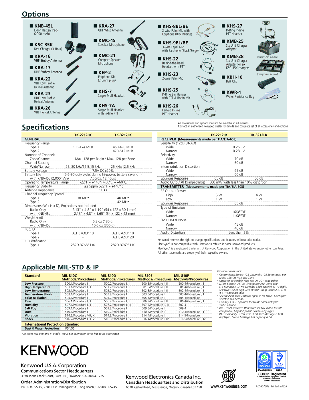
Options
■ | ■ | ■ | ■ | |
UHF Whip Antenna | ||||
(2000 mAh) |
| Earphone (Black/Beige) | PTT Headset | |
■ | ■ | ■ | ■ | |
Speaker Microphone | Six Unit Charger | |||
Fast Charger |
| Adapter | ||
| with Earphone (Black/Beige) | |||
|
|
|
■ | ■ | ■ | |
VHF Stubby Antenna | Compact Speaker | ||
| Microphone | ||
■ | ■ | Headset with PTT | |
UHF Stubby Antenna | ■ | ||
| Earphone Kit | ||
■ | |||
(2.5mm plug) | |||
VHF Low Profile |
|
| |
Helical Antenna | ■ | ■ | |
■ | |||
UHF Low Profile | with PTT & Boom Mic | ||
| |||
Helical Antenna |
|
|
■
Six Unit Charger
Adapter for six
■
Belt Clip
■
Water Resistance Bag
(chargers not included)
(chargers not included)
■ |
| ■ | ■ |
|
|
| ||
| Earbud |
|
|
| ||||
VHF Helical Antenna |
|
|
|
| ||||
| with | PTT Headset |
|
|
| |||
|
|
|
|
| ||||
Specifications |
|
|
| All accessories and options may not be available in all markets. | ||||
|
|
| Contact an authorized Kenwood dealer for details and complete list of all accessories and options. | |||||
|
|
|
|
| ||||
|
|
|
|
|
|
|
| |
|
|
|
|
|
|
|
|
|
|
|
|
|
| ||||
GENERAL |
|
|
|
| RECEIVER (Measurements made per |
| ||
Frequency Range |
|
|
|
| Sensitivity (12dB SINAD) |
|
|
|
Type 1 |
| Wide |
| 0.25 µV | ||||
Type 2 |
| - | Narrow |
| 0.28 µV | |||
Number of Channels |
|
|
|
| Selectivity |
|
|
|
Zone/Channel |
| Max. 128 per Radio / Max. 128 per Zone | Wide |
| 70 dB | |||
Channel Spacing |
|
|
|
| Narrow |
| 60 dB | |
Wide/Narrow | 25, 30 kHz/12.5,15 kHz | 25 kHz/12.5 kHz | Intermodulation Distortion |
|
|
| ||
Battery Voltage |
| 7.5V DC±20% | Wide |
| 65 dB | |||
Battery Life | Narrow |
| 60 dB | |||||
with | Approx. 12 hours | Spurious Response | 65 dB | 60 dB | ||||
Operating Temperature Range | ||
Frequency Stability | ±2.5ppm | |
Antenna Impedance |
| 50 Ω |
Channel Frequency Spread |
|
|
Type 1 | 38 MHz | 40 MHz |
Type 2 | - | 42 MHz |
Dimensions (W x H x D), Projections not Included |
| |
Radio Only | 2.13” x 4.8” x 1.19” (54 x 122 x 30.1 mm) | |
with | 2.13” x 4.8” x 1.65” (54 x 122 x 42 mm) | |
Weight (net) |
|
|
Radio Only | 6.3 oz (180 g) | |
with | 10.6 oz (300 g) | |
FCC ID |
|
|
Type 1 | ALH37683110 | ALH37693110 |
Type 2 | - | ALH37693120 |
IC Certification |
|
|
Type 1 | ||
Audio Output (8 Ω impedance) 500 mW with less than 10% distortion
TRANSMITTER (Measurements made per TIA/EIA-603)
RF Output Power |
|
|
High | 5 W | 4 W |
Low | 1 W | 1 W |
Spurious Response |
| 65 dB |
Type of Emission |
|
|
Wide |
| 16KØF3E |
Narrow |
| 11KØF3E |
FM HUM & Noise |
|
|
Wide |
| 45 dB |
Narrow |
| 40 dB |
Audio Distortion |
| Less than 5% |
Kenwood reserves the right to change specifications and features without prior notice. FleetSync® is not compatible with FleetSync II offered in some Kenwood products.
FleetSync® is a registered trademark of Kenwood Corporation in the United States and/or other countries. All other trademarks are property of their respective owners.
Applicable MIL-STD & IP
Standard | MIL 810C | MIL 810D | MIL 810E | MIL 810F |
| Methods/Procedures | Methods/Procedures | Methods/Procedures | Methods/Procedures |
Low Pressure | 500.1/Procedure I | 500.2/Procedure I, II | 500.3/Procedure I, II | 500.4/Procedure I, II |
High Temperature | 501.1/Procedure I, II | 501.2/Procedure I, II | 501.3/Procedure I, II | 501.4/Procedure I, II |
Low Temperature | 502.1/Procedure I | 502.2/Procedure I, II | 502.3/Procedure I, II | 502.4/Procedure I, II |
Temperature Shock | 503.1/Procedure I | 503.2/Procedure I | 503.3/Procedure I | 503.4/Procedure I, II |
Solar Radiation | 505.1/Procedure I | 505.2/Procedure I | 505.3/Procedure I | 505.4/Procedure I |
Rain | 506.1/Procedure I, II | 506.2/Procedure I, II | 506.3/Procedure I, II | 506.4/Procedure I, III |
Humidity | 507.1/Procedure I, II | 507.2/Procedure II, III | 507.3/Procedure II, III | 507.4 |
Salt Fog | 509.1/Procedure I | 509.2/Procedure I | 509.3/Procedure I | 509.4 |
Dust | 510.1/Procedure I | 510.2/Procedure I | 510.3/Procedure I | 510.4/Procedure I, III |
Vibration | 514.2/Procedure VIII, X | 514.3/Procedure I | 514.4/Procedure I | 514.5/Procedure I |
Shock | 516.2/Procedure I, II, V | 516.3/Procedure I, IV | 516.4/Procedure I, IV | 516.5/Procedure I, IV |
International Protection Standard
Dust & Water Protection IP54/55
*To meet MIL 810 and IP grade, the
Footnotes from front:
1Conventional Zones: 128 Channels /128 Zones max. per radio; 128 CH max. per Zone.
2Operator Selectable Tone (40 QT.DQT code pairs).
3DTMF Encode: PTT ID, Emergency ANI,
(16 numbers); ,DTMF Decode: Code Squelch
# & *) and radio Stun.
4Special Alert Tone Patterns operate for DTMF, FleetSync® selective call decode.
5Call Key 1 & 2: operates for DTMF and FleetSync® status encode.
6
7ID List capacity is 100 ID's; Short Text Message is LCD displayed; Status Message List capacity is 50.
ADS#07809 Printed in USA