Page 14
Examine the Front and Rear Panels
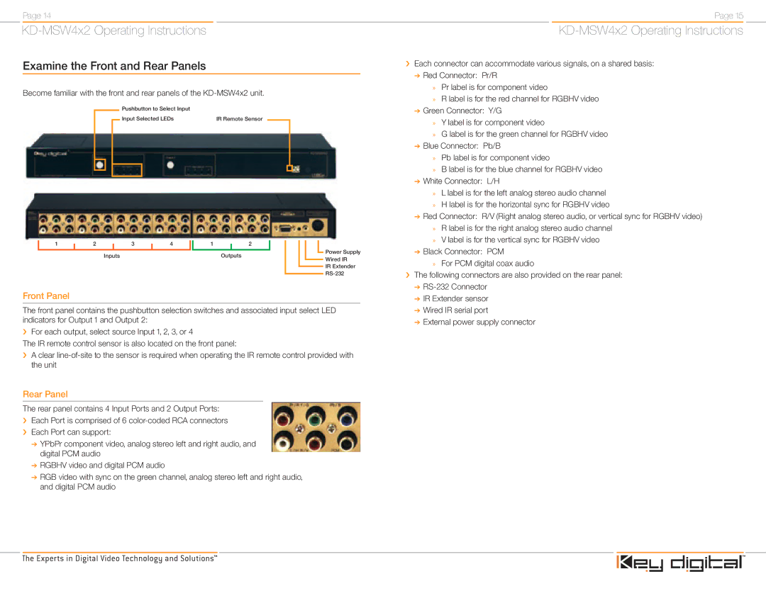
Become familiar with the front and rear panels of the
Pushbutton to Select Input |
|
Input Selected LEDs | IR Remote Sensor |
1 |
| 2 |
|
| 3 |
| 4 |
| 1 |
|
| 2 |
|
|
|
|
| Power Supply |
|
|
|
|
| ||||||||||||||
|
|
| Inputs |
|
|
|
| Outputs |
|
|
|
|
|
| ||||
|
|
|
|
|
|
|
|
|
|
|
|
| ||||||
|
|
|
|
|
|
|
|
|
|
|
|
| Wired IR | |||||
|
|
|
|
|
|
|
|
|
|
|
|
|
|
|
|
|
| |
|
|
|
|
|
|
|
|
|
|
|
|
|
|
|
|
|
| IR Extender |
|
|
|
|
|
|
|
|
|
|
|
|
|
|
|
|
|
| |
|
|
|
|
|
|
|
|
|
|
|
|
|
|
|
|
|
| |
|
|
|
|
|
|
|
|
|
|
|
|
|
|
|
|
|
| |
Front Panel
The front panel contains the pushbutton selection switches and associated input select LED indicators for Output 1 and Output 2:
›For each output, select source Input 1, 2, 3, or 4
The IR remote control sensor is also located on the front panel:
›A clear
Rear Panel
The rear panel contains 4 Input Ports and 2 Output Ports:
›Each Port is comprised of 6
›Each Port can support:
➔YPbPr component video, analog stereo left and right audio, and digital PCM audio
➔RGBHV video and digital PCM audio
➔RGB video with sync on the green channel, analog stereo left and right audio, and digital PCM audio
Page 15
›Each connector can accommodate various signals, on a shared basis:
➔Red Connector: Pr/R
»Pr label is for component video
»R label is for the red channel for RGBHV video
➔Green Connector: Y/G
»Y label is for component video
»G label is for the green channel for RGBHV video
➔Blue Connector: Pb/B
»Pb label is for component video
»B label is for the blue channel for RGBHV video
➔White Connector: L/H
»L label is for the left analog stereo audio channel
»H label is for the horizontal sync for RGBHV video
➔Red Connector: R/V (Right analog stereo audio, or vertical sync for RGBHV video)
»R label is for the right analog stereo audio channel
»V label is for the vertical sync for RGBHV video
➔Black Connector: PCM
»For PCM digital coax audio
›The following connectors are also provided on the rear panel:
➔
➔IR Extender sensor
➔Wired IR serial port
➔External power supply connector