Page 18

KD-MSW4x2 Operating Instructions

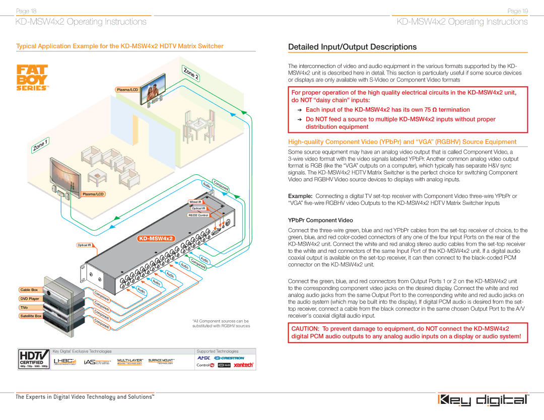
Typical Application Example for the KD-MSW4x2 HDTV Matrix Switcher

Zone2

Plasma/LCD


ne

1

Zo


Audio

Component

Plasma/LCD

Wired IR

Optical IR

RS232 Control

KD-MSW4x2

Page 19

KD-MSW4x2 Operating Instructions

Detailed Input/Output Descriptions

The interconnection of video and audio equipment in the various formats supported by the KD- MSW4x2 unit is described here in detail. This section is particularly useful if some source devices or displays are only available with S-Video or Component Video formats

For proper operation of the high quality electrical circuits in the KD-MSW4x2 unit, do NOT “daisy chain” inputs:

Each input of the KD-MSW4x2 has its own 75 Ω termination

Do NOT feed a source to multiple KD-MSW4x2 inputs without proper distribution equipment

High-quality Component Video (YPbPr) and “VGA” (RGBHV) Source Equipment

Some source equipment may have an analog video output that is called Component Video, a

3-wire video format with the video signals labeled YPbPr. Another common analog video output format is RGB (like the “VGA” outputs on a computer), which typically has separate H&V sync signals. The KD-MSW4x2 HDTV Matrix Switcher is the perfect choice for switching Component Video and RGBHV Video source devices to displays with analog inputs.

Example: Connecting a digital TV set-top receiver with Component Video three-wire YPbPr or “VGA” five-wire RGBHV video Outputs to the KD-MSW4x2 HDTV Matrix Switcher Inputs

YPbPr Component Video

Connect the three-wire green, blue and red YPbPr cables from the set-top receiver of choice, to the green, blue, and red color-coded connectors of any one of the four Input Ports on the rear of the

Cable Box

DVD Player

TiVo

Satellite Box

Optical IR

Component

Component

Component

Component

Audio

Audio Component

Audio

Audio

Audio

*All Component sources can be substituted with RGBHV sources

KD-MSW4x2 unit. Connect the white and red analog stereo audio cables from the set-top receiver to the white and red connectors of the same Input Port of the KD-MSW4x2 unit. If a digital audio coaxial output is available on the set-top receiver, it can then connect to the black-coded PCM connector on the KD-MSW4x2 unit.

Connect the green, blue, and red connectors from Output Ports 1 or 2 on the KD-MSW4x2 unit to the corresponding component video jacks on the desired display. Connect the white and red analog audio jacks from the same Output Port to the corresponding white and red audio jacks on the audio system (which may be built into the display). If digital PCM audio is desired from the set- top receiver, connect a cable from the black connector in the same chosen Output Port to the A/V receiver's coaxial digital audio input.

CAUTION: To prevent damage to equipment, do NOT connect the KD-MSW4x2 digital PCM audio outputs to any analog audio inputs on a display or audio system!

Key Digital® Exclusive Technologies

Supported Technologies

Page 11
Image 11
Key Digital KD-MSW4X2 operating instructions Zone2, Detailed Input/Output Descriptions