Assembly
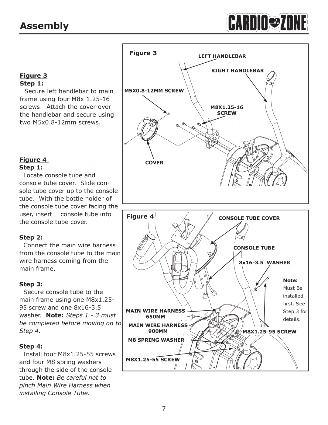
Figure 3
Step 1:
Secure left handlebar to main frame using four M8x
Figure 4
Step 1:
Locate console tube and console tube cover. Slide con- sole tube cover up to the console tube. With the bottle holder of the console tube cover facing the user, insert console tube into the console tube cover.
Step 2:
Connect the main wire harness from the console tube to the main wire harness coming from the main frame.
Step 3:
Secure console tube to the main frame using one M8x1.25- 95 screw and one
Step 4:
Install four
|
|
|
|
|
Figure 3 |
|
|
| |
LEFT HANDLEBAR |
| |||
|
|
| ||
|
|
|
|
|
|
|
|
|
|
|
|
| RIGHT HANDLEBAR | |
|
|
| |
| SCREW |
COVER |
|
Figure 4 | CONSOLE TUBE COVER |
| CONSOLE TUBE |
| |
| Note: |
| Must Be |
| installed |
| first. See |
MAIN WIRE HARNESS | Step 3 for |
650MM | details. |
| |
MAIN WIRE HARNESS |
|
900MM | |
M8 SPRING WASHER |
|
|
