www.keysfitness.com |
|
|
Use Tool |
| J |
| Use Tool |
|
| 13mm | D |
| 14mm | |
6mm |
| J1 |
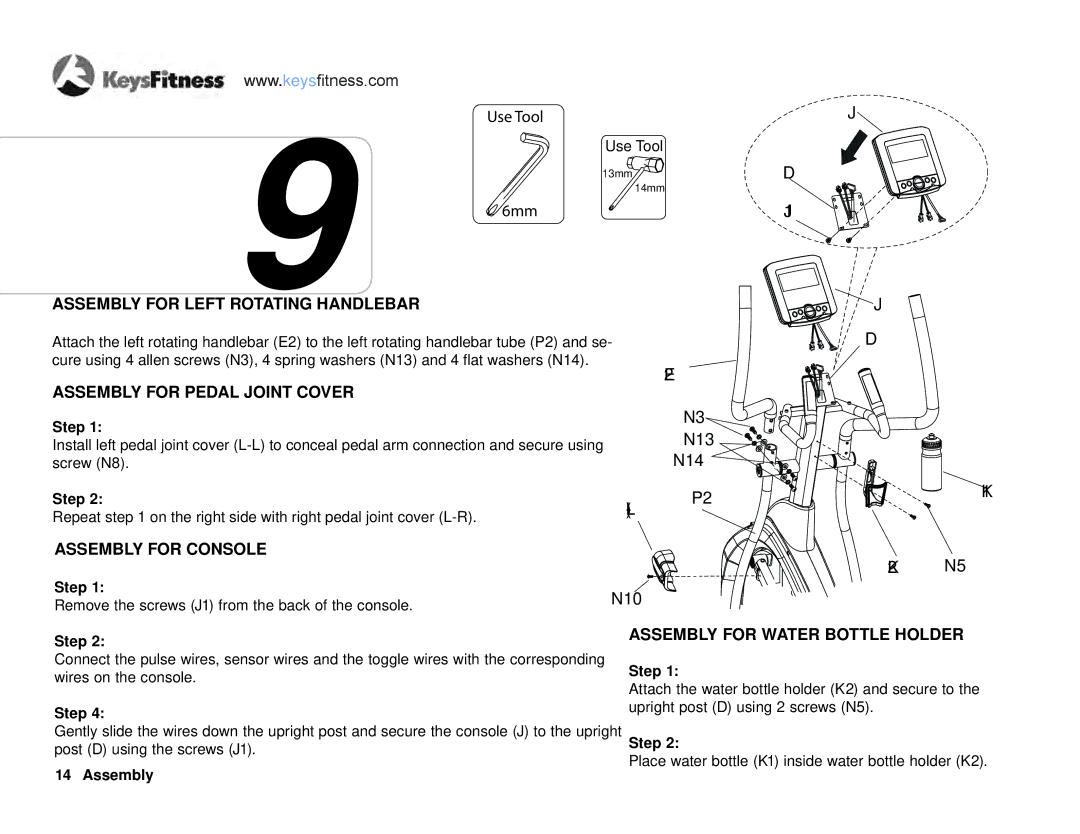
ASSEMBLY FOR LEFT ROTATING HANDLEBAR |
| J |
Attach the left rotating handlebar9(E2) to the left rotating handlebar tube (P2) and se- | D | |
cure using 4 allen screws (N3), 4 spring washers (N13) and 4 flat washers (N14). |
| E2 |
ASSEMBLY FOR PEDAL JOINT COVER |
| |
|
| |
Step 1: |
| N3 |
| N13 | |
Install left pedal joint cover | ||
screw (N8). |
| N14 |
Step 2: | P2 | |
Repeat step 1 on the right side with right pedal joint cover |
| |
|
| |
ASSEMBLY FOR CONSOLE |
| K2 |
Step 1: |
| |
N10 |
| |
Remove the screws (J1) from the back of the console. |
| |
|
| |
K1
N5
Step 2:
Connect the pulse wires, sensor wires and the toggle wires with the corresponding wires on the console.
Step 4:
Gently slide the wires down the upright post and secure the console (J) to the upright post (D) using the screws (J1).
14 Assembly
ASSEMBLY FOR WATER BOTTLE HOLDER
Step 1:
Attach the water bottle holder (K2) and secure to the upright post (D) using 2 screws (N5).
Step 2:
Place water bottle (K1) inside water bottle holder (K2).