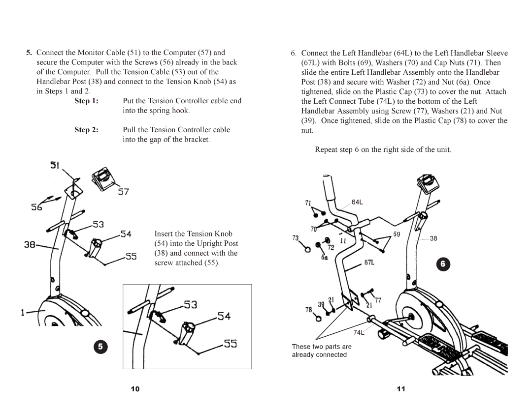
5.Connect the Monitor Cable (51) to the Computer (57) and secure the Computer with the Screws (56) already in the back
of the Computer. Pull the Tension Cable (53) out of the Handlebar Post (38) and connect to the Tension Knob (54) as in Steps 1 and 2:
Step 1:
Step 2:
5
6.Connect the Left Handlebar (64L) to the Left Handlebar Sleeve (67L) with Bolts (69), Washers (70) and Cap Nuts (71). Then slide the entire Left Handlebar Assembly onto the Handlebar Post (38) and secure with Washer (72) and Nut (6a). Once tightened, slide on the Plastic Cap (73) to cover the nut. Attach the Left Connect Tube (74L) to the bottom of the Left Handlebar Assembly using Screw (77), Washers (21) and Nut (39). Once tightened, slide on the Plastic Cap (78) to cover the nut.
Repeat step 6 on the right side of the unit.
64L
38
6
74L
These two parts are already connected
10 | 11 |