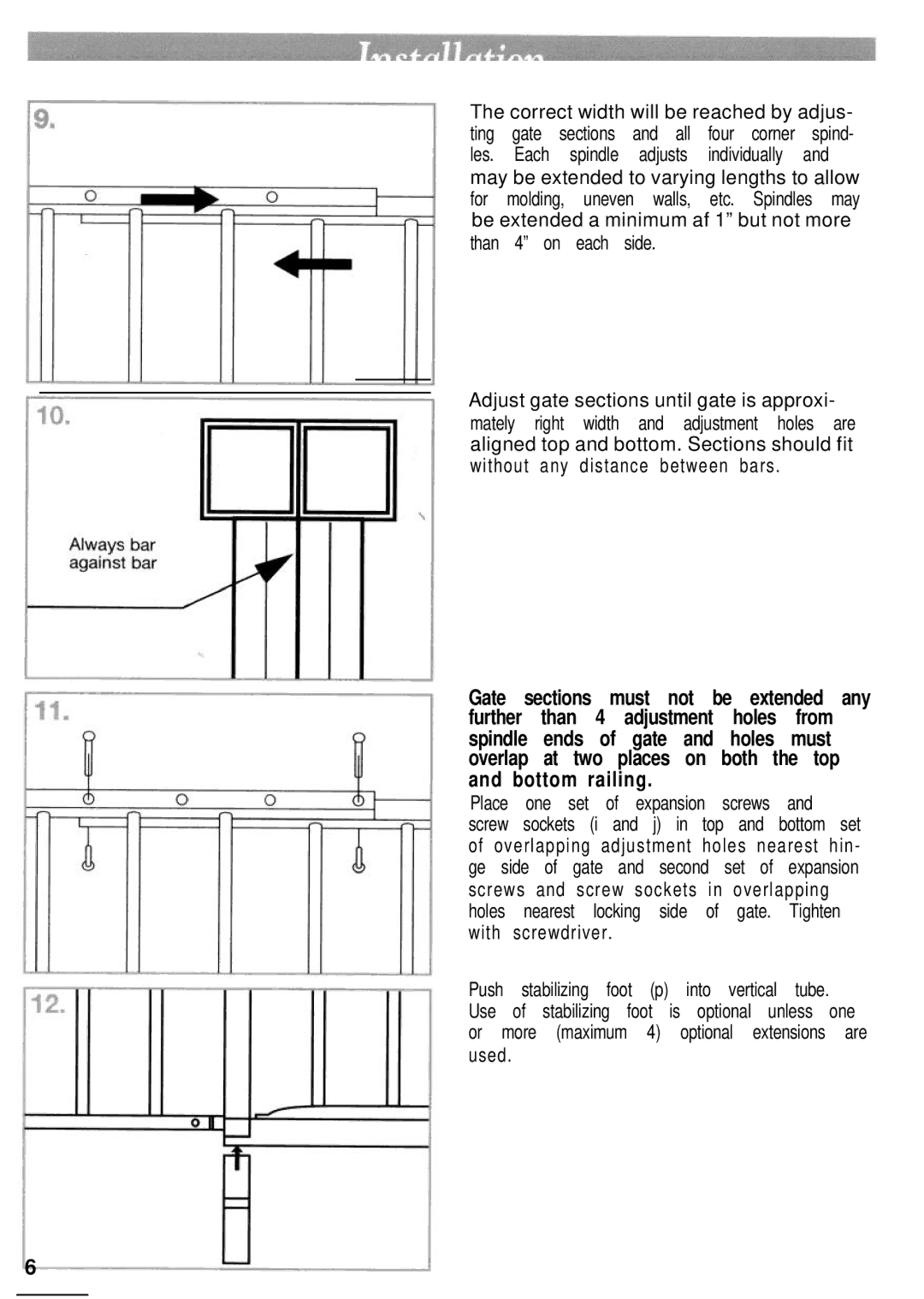
The correct width will be reached by adjus-
ting | gate | sections | and all | four corner | spind- |
les. | Each | spindle | adjusts | individually | and |
may be extended to varying lengths to allow for molding, uneven walls, etc. Spindles may be extended a minimum af 1” but not more than 4” on each side.
Adjust gate sections until gate is approxi- mately right width and adjustment holes are aligned top and bottom. Sections should fit without any distance between bars .
Gate sections must not be extended any further than 4 adjustment holes from spindle ends of gate and holes must overlap at two places on both the top and bottom railing.
Place one set of expansion screws and
screw sockets (i and j) in top and bottom set of overlapping adjustment holes nearest hin -
ge side of gate and | second | set | of | expansion | ||||||
screws and screw sockets in overlapping |
| |||||||||
holes | nearest | locking | side | of | gate. | Tighten | ||||
with | screwdriver . |
|
|
|
|
|
|
| ||
Push | stabilizing | foot | (p) | into | vertical | tube. |
| |||
Use | of | stabilizing foot | is | optional | unless | one | ||||
or more | (maximum | 4) | optional | extensions | are | |||||
used. |
|
|
|
|
|
|
|
|
|
|
6