Manuals
/
Graco
/
Kitchen Appliance
/
Water Dispenser
Graco
PR70 Manual: Wiring Diagrams and User Instructions
Models:
PR70
1
47
50
50
Download
50 pages
58.39 Kb
43
44
45
46
47
48
49
50
Page 47
Image 47
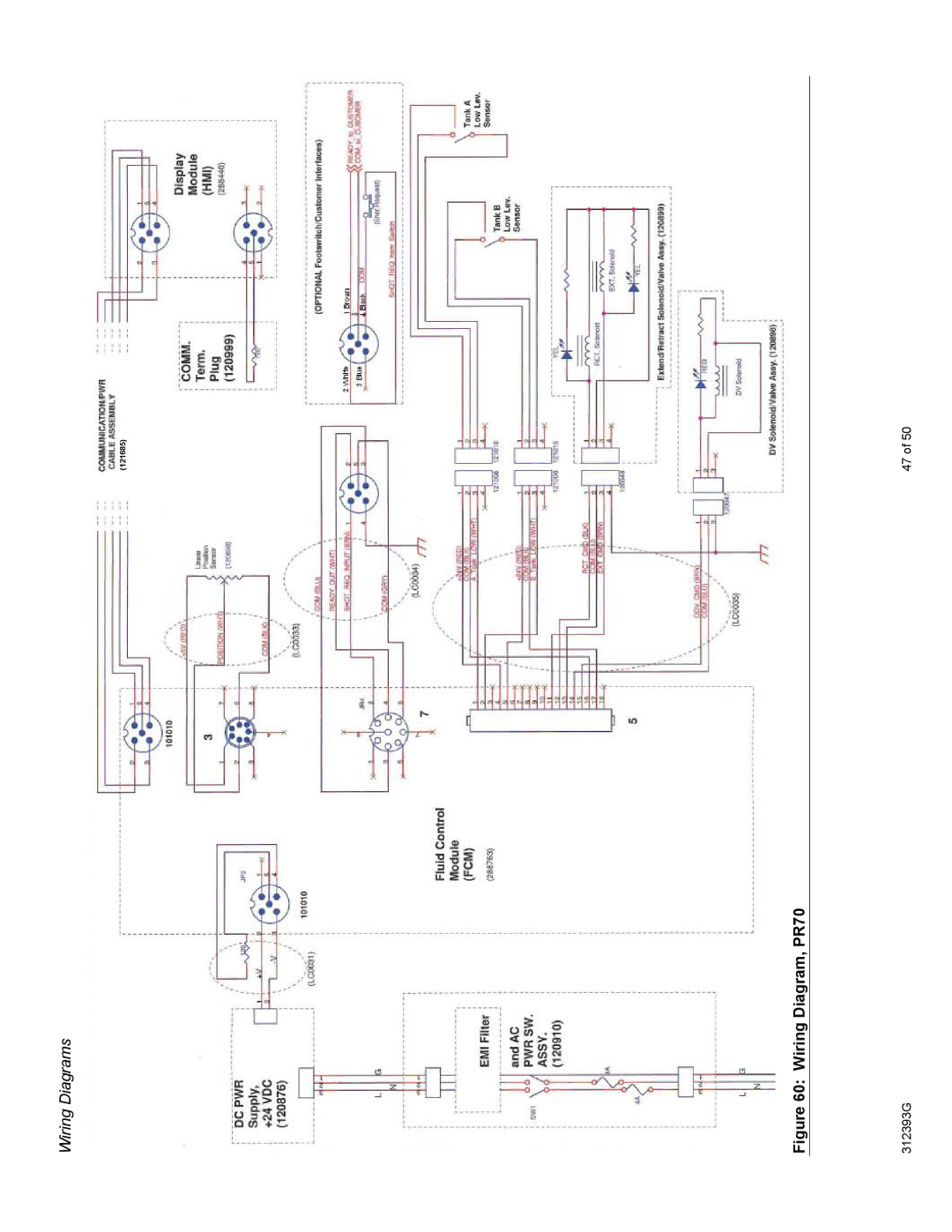
Wiring Diagrams
(121685)
Figure 60: Wiring Diagram, PR70
312393G
47 of 50
Page 46
Page 48
Page 47
Image 47
Page 46
Page 48
Contents
PR70
Contents
Mixer and Shroud Options
PR70 Accessories
Description
Supplied Manuals
Related Manuals
PR70 Feed System
Electric Shock Hazard
Equipment Misuse Hazard
General Information
Installation
Locate and Install the PR70
Machine Setup
Key
Component Identification
PR70 Top View with Shield, Tanks, DV and HMI Removed
HMI Control and Indicators
Run Screen Operation
Setup Screens with Passwords Enabled
Machine Disable Mode red
Setup Screens
Entering the Setup Screens
PR70 Screen Navigation Diagram
Piston Position Calibration C1
Machine Priming
Machine Calibration
Phasing C2
Open Dispense Valve ODV Setting C3
Open Dispense Valve ODV Screen C3 Key
Machine Calibration Shots C4
Ratio Checks
Shot Size Definition M2
Manual DV Control
Miscellaneous Machine Setups
Purge Timer / Alarm Settings M2
Manual Control Options M1
M2 after Purge Shot Size Prompt
Cycle Counter and Silent Mode Control M3
Tank Level Sensing and Velocity Change Options C6
Date and Time Settings M4
Setting/Clearing an Administrative Password
Password Setup / Clearing C5
To clear the password, enter
Setting/Clearing a Maintenance only Password
Resetting Passwords
Limitations of Demo Mode Simulation
Miscellaneous Machine Features
HMI Hibernate Mode
HMI Demo Mode Operation
Error Codes
Pressure Relief Procedure
Standby/Shutdown Procedure
Error Code Table
E50
Error Code Table
E29
Tables 3 PR70 Screen Icon Tables
Key Key Description Screen
PR70 HMI Icon Table
Tables 4 PR70 Screen Icon Tables
Run Token
Maintenance
Software Upgrades, Run Token
Problem Cause Solution
Troubleshooting
Major Mechanical Assemblies, and Attachments
Repair
PR70 Base Frame Assembly LC0109 Key
Base Frame Assembly
Air Cylinder Assemblies, and Rebuild Kits
PR70 Air Cylinder System and Schematic
Air Cylinder Assemblies
Pump Assembly
Pump Assemblies and Rebuild Kits
Drive Block Assembly
PR70 Check Valve Rebuild Kit LC0093 Key
To install a new Check Valve Rebuild Kit
PR70 Rear Pump Rebuild Kit LC0094 Key
To install a new Rear Pump Rebuild Kit
Piston Cylinders or Metering Tubes
PR70 Nylon and Uhmwpe Piston Replacement Kits Key
Nylon Pistons see Figure
To install a new Piston or Piston/Cylinder Replacement Kit
Available PR70 Piston and Cylinder Metering Tubes Kits Key
Hose Assemblies
To install a new Piston Plug Assembly
Heated Piston to DV Hose Assemblies
To Replace the Fuses
Miscellaneous Mechanical Assemblies
PR70 Control Bracket Assembly LC0108 Key
PR70 Hydracheck Components
PR70 Wiring Interconnect Illustration
Wiring Diagrams
Wiring Diagram, PR70
Category Data
Technical Data
PR70 Dimensions ON-Board PE Tank version Illustrated
Dimensions
Graco Information
Graco Ohio Standard Warranty
Top
Page
Image
Contents