Pump Assembly
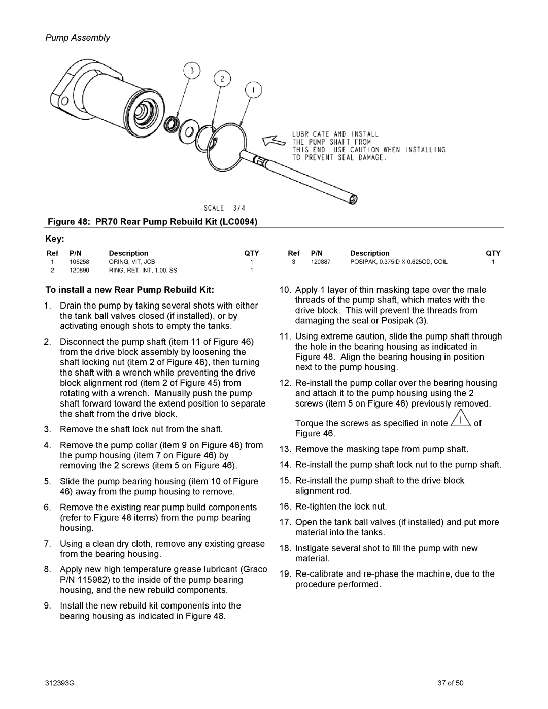
Figure 48: PR70 Rear Pump Rebuild Kit (LC0094)
Key:
Ref | P/N | Description | QTY | Ref | P/N | Description | QTY |
1 | 106258 | ORING, VIT, JCB | 1 | 3 | 120887 | POSIPAK, 0.375ID X 0.625OD, COIL | 1 |
2 | 120890 | RING, RET, INT, 1.00, SS | 1 |
|
|
|
|
To install a new Rear Pump Rebuild Kit:
1.Drain the pump by taking several shots with either the tank ball valves closed (if installed), or by activating enough shots to empty the tanks.
2.Disconnect the pump shaft (item 11 of Figure 46) from the drive block assembly by loosening the shaft locking nut (item 2 of Figure 46), then turning the shaft with a wrench while preventing the drive block alignment rod (item 2 of Figure 45) from rotating with a wrench. Manually push the pump shaft forward toward the extend position to separate the shaft from the drive block.
3.Remove the shaft lock nut from the shaft.
4.Remove the pump collar (item 9 on Figure 46) from the pump housing (item 7 on Figure 46) by removing the 2 screws (item 5 on Figure 46).
5.Slide the pump bearing housing (item 10 of Figure 46) away from the pump housing to remove.
6.Remove the existing rear pump build components (refer to Figure 48 items) from the pump bearing housing.
7.Using a clean dry cloth, remove any existing grease from the bearing housing.
8.Apply new high temperature grease lubricant (Graco P/N 115982) to the inside of the pump bearing housing, and the new rebuild components.
9.Install the new rebuild kit components into the bearing housing as indicated in Figure 48.
10.Apply 1 layer of thin masking tape over the male threads of the pump shaft, which mates with the drive block. This will prevent the threads from damaging the seal or Posipak (3).
11.Using extreme caution, slide the pump shaft through the hole in the bearing housing as indicated in Figure 48. Align the bearing housing in position next to the pump housing.
12.
Torque the screws as specified in note ![]() of Figure 46.
of Figure 46.
13.Remove the masking tape from pump shaft.
14.
15.
16.
17.Open the tank ball valves (if installed) and put more material into the tanks.
18.Instigate several shot to fill the pump with new material.
19.
312393G | 37 of 50 |
